Site pages
Current course
Participants
General
MODULE 1. Electro motive force, reluctance, laws o...
MODULE 2. Hysteresis and eddy current losses
MODULE 3. Transformer: principle of working, const...
MODULE 4. EMF equation, phase diagram on load, lea...
MODULE 5. Power and energy efficiency, open circui...
MODULE 6. Operation and performance of DC machine ...
MODULE 7. EMF and torque equations, armature react...
MODULE 8. DC motor characteristics, starting of sh...
MODULE 9. Polyphase systems, generation - three ph...
MODULE 10. Polyphase induction motor: construction...
MODULE 11. Phase diagram, effect of rotor resistan...
MODULE 12. Single phase induction motor: double fi...
MODULE 13. Disadvantage of low power factor and po...
MODULE 14. Various methods of single and three pha...
LESSON 32. Methods of three phase power measurement
Measurement of Power in THREE PHASE SYSTEM
Three-wattmeter Method: Let the load coils in figure 14.4 be the three coils of either a Y-connected alternator or of a Y-connected load.
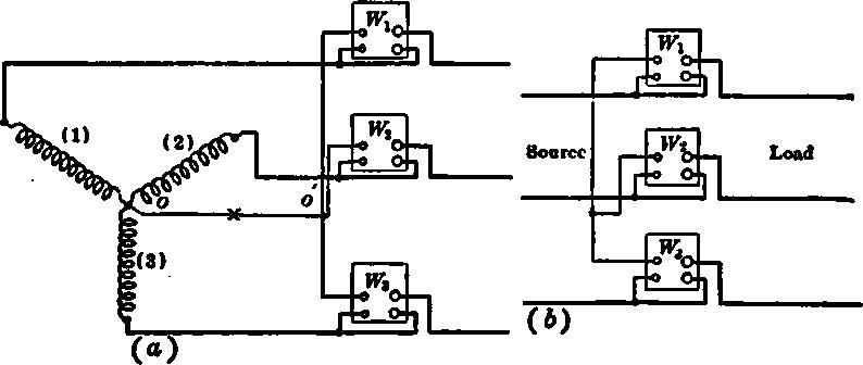
Fig. 14.4 The 3-wattmeter method of measuring 3-phase power.
If the neutral of the Y is accessible, it is possible to measure the power of each phase by connecting the current-coil of a wattmeter in series with the phase and by connecting the wattmeter potential-coil across the phase. Therefore ,W1, W2 and W3 measure the power in load coils 1, 2, and 3 respectively, regardless of power-factor, degree of balance, etc. The total power
P = W1 + W2 + W3
If the potential circuits of the three wattmeters have equal resistances, these three potential circuits constitute a balanced Y-load, having a neutral. As coils 1, 2, and 3 and these three wattmeter potential-circuits are both symmetrical systems, neutral of their connection must be at the same potential as 0. Therefore, no current flows between these two neutrals and the line can be cut at without changing existing conditions. Figure below shows the three wattmeter connection for a three phase system. It can be shown that the total power is the sum of the wattmeter readings even though the wattmeter potential circuits have different resistances. Under these conditions, however, the wattmeters may not all have the same reading, even with balanced loads. The three wattmeter method is well adapted to measuring power in a system where the power-factor is continually changing, as in obtaining the phase characteristics of a synchronous motor. If the three instruments have equal potential-circuit resistances, they read alike regardless of power-factor, if the loads are balanced. The three wattmeter method is necessary in a three-phase four-wire system, as a system of n wires ordinarily requires n — 1 wattmeters in order to measure the power correctly.
Two-wattmeter Method.
The power in a three-wire, three-phase system can be measured by two wattmeters connected as shown in Figure 14.5. The current-coils of the two instruments are connected in two of the lines and the potential-coil of each instrument is connected from its respective line to the third line. Two-wattmeter method of measuring 3-phase power.
Under these conditions the total power passing through the system
p = W1 ± W2
regardless of power-factor, balance, etc.
One method of proving that these instruments give the correct power is as follows: Let e1,e2, e3 and i1, i2 , i3 be the respective voltages and currents of the three loads at any particular instant. These being instantaneous values, the power at the instant under consideration is equal to their products regardless of power-factor. That is, the instantaneous power
P = p = e1 i1 + e2 i2 + e3 i3
But
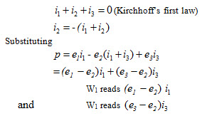
The same proof may be used for a delta-load, except that
ei + e2 + cz = 0
It can be shown that a phase difference of 30° exists between the line voltage and line current at unity power factor.
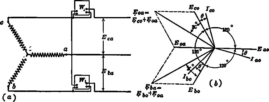
Fig. 14.5 Vector diagram illustrating 2-wattmeter method for measuring 3-phase power, balanced load.
For power-factors other than unity, this phase difference becomes (30° ± φ), where j is the power factor angle of the coil. Figure shows two watt meters, W1 and W2, measuring the power taken by a balanced three-phase, Y-connected load. The wattmeter W1 is so connected that the current ib flows in its current coil and the voltage Eba is across its potential-circuit. Therefore, the reading of W1 is equal to the product of ib , Eba and the cosine of the angle between this current and this voltage. Figure shows the vector diagram of the load also. The three coil voltages Eao, Ebo, and Eco are all equal and 120° apart. The coil currents Ia,, Ib and Ic are equal and lag their respective coil voltages by the angle j. The voltage Eba is found by reversing Eao, giving Eoa, and then adding Ebo and Eoa vectorially (Eba = Ebo + Eoa). The current Ibo is given. The angle between Eba and Ibo is 30°- φ. Therefore, the reading of this wattmeter is
W1 = Eba Ibo cos (30° - φ) = Eline Iline cos (30° - φ)
Likewise, the wattmeter W2 reads the product of Eca, Ico and the cosine of the angle between them. From the vector diagram, the angle between Eca and Ico is 30° + j . Eca is found by adding vectorially Eco and Eoa.
Therefore the reading of this wattmeter is
W2 = Eca Ico cos (30° + 0) = EUne Iline cos (30° + φ)
Summarizing
W1 = EI cos (30° - φ) ; W2 = EI cos (30° + φ)
where E and I are the line voltage and line current, respectively, the system being balanced.
W1 and W2 will read alike when φ = 0 and φ = 180°. Both conditions correspond to unity power factor. When φ equals 180°, however, the power has reversed. The two instruments also read alike at zero power-factor (φ = 90°), although this condition is never realized.
When φ = 60°, corresponding to a power-factor of 0.5, Wt reads zero, as cos (30° + 60°) = cos 90° = 0. In this case, the reading of W1 gives the total power. For angles greater than 60°, corresponding to power factors less than 0.5, cos (30° +φ) becomes negative, W2 reads negative and the total power becomes
p = W1 – W2
Therefore, discretion must be used when two single instruments are employed, as the total power may be either the sum or the difference of the readings.
It may also be shown that
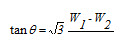
where φ is the load’s power factor angle. Therefore it is possible to obtain the power factor in a balanced three-phase system by means of the wattmeter readings alone.
Example.—In a test of a three phase induction motor, two watt meters are used to measure the input. Their readings are 1,900 and 800 watts respectively. Both instruments are known to be reading positive. What is the power-factor of the motor at this load?
tan φ = √3 (1900-800)/(1900+800) = 0.705
φ = = 35.3°
cos 35.3° = 0.815.
The two-wattmeter method cannot be used to measure power in a three-phase, four-wire system unless the current in the neutral wire is zero (Fig. 14.6). When the current in the neutral wire of figure below is zero, the power is correctly indicated by W1 ± W2.
If we apply load B'O between line B and the neutral, the current to this load will complete its circuit from wire B through the neutral without going through the current coil of either watt meter. As neither wattmeter can indicate this additional load, the two watt meters are not sufficient to measure the power in such a four wire system under all conditions of load.
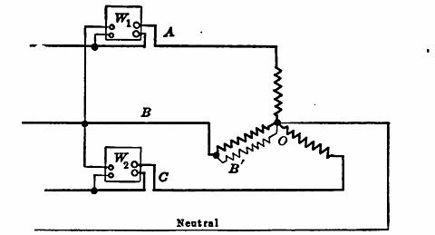
Fig. 14.6 Two-wattmeter method generally not applicable to a 4-wire system.
Poly phase Wattmeter:
Ordinarily, it requires two or more watt meters to measure the total power of a three phase circuit. If the load fluctuates, it is difficult to obtain accurate simultaneous readings of two watt meters. At power factors less than 0.5 in the three phase circuit, one of the wattmeters reverses its reading.
This necessitates reversing the connections of one of the instruments, which is often inconvenient. If both watt meters be combined in one, that is, if both moving coils are mounted on the same spindle (Fig. 14.7), the turning moments for each element add or subtract automatically, and the total power is read on a single scale.
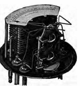
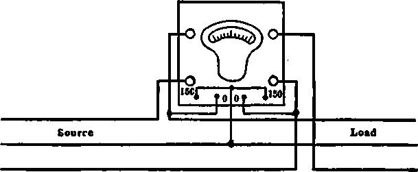
Fig. 14.7 Connections for poly phase wattmeter on 3-phase circuit