Site pages
Current course
Participants
General
MODULE 1. Introduction to production of agricultur...
MODULE 2. Advance in material for tractor and agri...
MODULE 3. Advanced manufacturing techniques
MODULE 4. Heat treatment of steel
MODULE 5. Industrial lay out planning and quality ...
MODULE 6. Economics of process
MODULE 7. Techno economic feasibility of project r...
MODULE 8. Servo motors, drives and controllers
MODULE 9. CNC controllers for machine tools
MODULE 10. CNC programming
MODULE 11. Assembly and plant automation storage a...
LESSON 7. ELECTRICAL DISCHARGE MACHINING (EDM)
2.1. Introduction
It is an advanced machining process primarily used for hard and difficult metals which are difficult to machine with the traditional techniques. Only electrically conducting materials are machined by this process. The EDM process is best suited for making intricate cavities and contours which would be difficult to produce with normal machines like grinders, end-mills or other cutting tools. Metals such as hardened tool-steels, carbides, titanium, inconel and kovar are easily machined through EDM.
EDM is a thermal process which makes use of spark discharges to erode the material from work piece surface. The cavity formed in EDM is a replica of the tool shape used as the erosions occur in the confined area. Since spark discharges occur in EDM, it is also called as "spark machining". The material removal takes place in EDM through a rapid series of electrical discharges. These discharges pass between the electrode and the work piece being machined. The fine chips of material removed from the work piece gets flushed away by the continuous flowing di-electric fluid. The repetitive discharge creates a set of successively deeper craters in the work piece until the final shape is produced.
2.2. EDM Principle
The schematic of the basic EDM process is illustrated in Fig. 3.2.1. In this process, the work piece and tool are submerged into a non-conducting, dielectric fluid which is separated by a small gap (for sparking). The dielectric fluid insulates the work piece from the tool and creates the resistance of electricity flow between the electrodes. The dielectric fluid may be typical hydrocarbon oil (kerosene oil) or de-ionized water. It also helps in cooling down the tool and workpiece, clears the inter-electrode gap (IEG), and concentrates the spark energy to a small cross sectional area under the electrode.
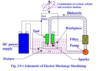
Fig. 3.2.1.Schematic of electric discharge machining
As the two electrodes come closer to one another, the electric field intensity increases beyond the strength of the dielectric enabling it to break and thereby allow the current to flow between the two electrodes. As a result of this effect, intense heat gets generated near the zone, which melts and evaporates the material in the sparking zone. As the flow of current is momentarily stopped, some fresh dielectric liquid particles come in position between the inter-electrode gap which restores the insulating properties of the dielectric. The solid particles (debris) are carried away by the flowing dielectric. Flushing refers to the addition of new liquid dielectric to the inter-electrode volume. A close view of the EDM process is shown in Fig. 3.2.2. The sparks occur at spots where the tool and the workpiece surfaces are the closest and since the spots change after each spark (because of the material removal after each spark), the spark travels all over the surfaces. This results in uniform removal of material, hence exact shape get reproduced on the workpiece surface.
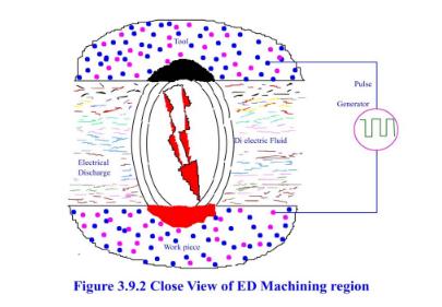
Fig. 3.2.2 Close view of EDM region
2.3. Advantages of EDM
The major advantages of the process are:
-
Any materials that are electrically conductive can be machined by EDM.
-
Materials, regardless of their hardness, strength, toughness and microstructure can be easily machined / cut by EDM process
-
The tool (electrode) and workpiece are free from cutting forces
-
Edge machining and sharp corners are possible in EDM process
-
The tool making is easier as it can be made from softer and easily formable materials like copper, brass and graphite.
-
The process produces good surface finish, accuracy and repeatability.
-
Hardened work-pieces can also be machined since the deformation caused by it does not affect the final dimensions.
-
EDM is a burr free process.
-
Hard die materials with complicated shapes can be easily finished with good surface finish and accuracy through EDM process.
-
Due to the presence of dielectric fluid, there is very little heating of the bulk material.
2.4. Limitations of EDM
Material removal rates are low, making the process economical only for very hard and difficult to machine materials.
-
Re-cast layers and microcracks are inherent features of the EDM process, thereby making the surface quality poor.
-
The EDM process is not suitable for non-conductors.
-
Rapid electrode wear makes the process more costly.
-
The surfaces produced by EDM generally have a matt type appearance, requiring further polishing to attain a glossy finish.
2.5. Applications of EDM
-
Hardened steel dies, stamping tools, wire drawing and extrusion dies, header dies, forging dies, intricate mould cavities and such parts are made by the EDM process.
-
The process is widely used for machining of exotic materials that are used in aerospace and automatic industries.
-
EDM being a non-contact type of machining process, it is very well suited for making fragile parts which cannot take the stress of machining. The parts that fit such profiles include washing machine agitators; electronic components, printer parts and difficult to machine features such as the honeycomb shapes. Deep cavities, slots and ribs can be easily made by EDM as the cutting forces are less and longer electrodes can be used to make such collets, jet engine blade slots, mould cooling slots etc.
-
Micro-EDM process can successfully produce micro-pins, micro-nozzles and micro-cavities.
2.6. Mechanism of Material Removal in EDM
In EDM, for a particular machining condition there are numerous phenomena involved, i.e., heat conduction and radiation, phase changes, electrical forces, bubble formation and collapse, rapid solidification etc. Thermo-electric phenomenon is the most appropriate theory for the explanation of the electrical discharge machining process. The removal of material in EDM is associated with the erosive effects produced when discrete and spatial discharge occurs between the tool and workpiece electrodes. Short duration sparks are generated between these two electrodes. The generator releases electrical energy, which is responsible for melting a small quantity of material from both the electrodes. At the end of the pulse duration, a pause time begins. The forces that may be of electric, hydrodynamic and thermodynamic in nature remove the melted pools. The material removal process by a single spark is as follows:
An intense electric field develops in the gap between electrode and workpiece.
There are some contaminants inside the dielectric fluid which build a high-conductivity bridge between the electrode and workpiece.
When the voltage increases, the bridge and dielectric fluid between the electrode and workpiece heat up. The dielectric is ionized to form a spark channel. The temperature and pressure rapidly increase and a spark is generated. A small amount of material is evaporated on the electrode and workpiece at the spark contact point.
Bubbles rapidly expand and explode during sparking until the voltage is turned off. Next the heating channel collapses and the dielectric fluid enters into the gap in-order to flush away the molten metal particles.
The material removal rate depends on the following factors:
Peak amperage or intensity of the spark
Length of the ON time
OFF time influences the speed and stability
Duty cycle: percentage of on-time relative to total cycle time
- Gap distance: Smaller the gap better is the accuracy and slower is the material removal rate.
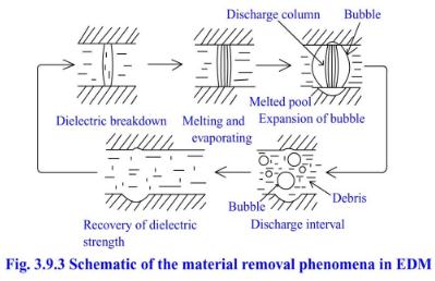
The material removal phenomena in EDM are shown schematically in the Fig. 3.2.3
2.7. Types of EDM Processes
1. Die Sinker EDM
2. Wire Cut EDM
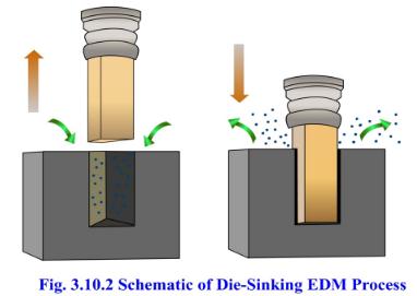
2.7.1. Die-Sinker EDM and its Systems
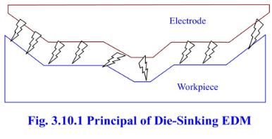
Die-Sinker EDM is known by different names such as Ram EDM, sinker EDM, vertical EDM and plunge EDM. The process is generally used for producing blind cavities. In die-sinker EDM, the electrode and workpiece are submerged in an insulating liquid such as oil or other dielectric fluids. The electrode and workpiece are connected to a suitable power supply. An electrical potential is generated between the tool and the workpiece through the power supply. As the electrode approaches workpiece, the dielectric break down starts taking place in the fluid. Due to this activity, a plasma channel starts forming and sparks jump from the electrode to the workpiece leading to material removal from the workpiece. The principle of die-sinking EDM is shown in Fig. 3.2.4 and the schematic of die-sinker EDM process is shown in Fig. 3.2.5.
The main components of Die-sinker EDM are:
Power supply.
Dielectric system.
Electrode
Servo system.
Power Supply
The power supply provides a series of DC electrical discharges and controls:
Current
Pulse voltage
Pulse duration
Duty cycle
Electrode polarity
Pulse frequency
Dielectric and its Circulation System
The dielectric fluids used in EDM operations are of different types. The most popular dielectric fluids are hydrocarbon oil (kerosene in particular). The other fluids used are transformer oil, paraffin oil; silicon based oil, or de-ionized water. The selection of an appropriate dielectric fluid depends upon its various chemical and fluidic properties (such as flash point, dielectric strength, viscosity, specific gravity and color) The dielectric system performs the following tasks:
- It induces clean dielectric into the cutting zone
- Flushes away debris
- Cools the workpiece and electrodes
In order to provide circulation of the dielectric fluid to the work piece, the EDM machine tool is equipped with a well-designed dielectric circulation system. It consists of following two parts:
1. Pump : Its main purpose is to circulate the dielectric fluid on-to the workpiece
2. Filter and suction unit: This unit filters out the material debris and any other foreign parts from the dielectric.
Servo System
The servo system is commanded by signals from gap voltage sensor system in the power supply and it controls the in-feed of the electrode to precisely match the required rate of material removal. At times stepper motor can be used instead of a servomotor. As soon as the gap voltage sensor system determines bridging of some pieces of electrically conductive materials between the electrode and work-piece, the servo system immediately reacts and reverses the direction. The process is restored when the gap is flushed by the dielectric fluid. When the gap becomes clear, the in-feed resumes and cutting process continues.
Electrodes
The electrodes for EDM process are usually made of brass, copper, graphite and copper-tungsten alloys.
Design considerations for EDM process
In EDM process, fine openings and deeper slots need to be avoided.
Very fine surface finish values should not be specified.
As the MRR of EDM process is low, the rough cutting should be done by some other machining process and EDM machine should me made used for the finishing operations only.
2.7.2. Wire Cut Electric Discharge Machining (WEDM)
The Wire Electric Discharge Machining (WEDM) is a variation of EDM and is commonly known as wire-cut EDM or wire cutting. In this process, a thin metallic wire is fed on-to the workpiece, which is submerged in a tank of dielectric fluid such as de-ionized water. This process can also cut plates as thick as 300mm and is used for making punches, tools and dies from hard metals that are difficult to machine with other methods. The wire, which is constantly fed from a spool, is held between upper and lower diamond guides. The guides are usually CNC-controlled and move in the x–y plane. On most machines, the upper guide can move independently in the z–u–v axis, giving it a flexibility to cut tapered and transitioning shapes (example: square at the bottom and circle on the top). The upper guide can control axis movements in x–y–u–v–i–j–k–l–. This helps in programming the wire-cut EDM, for cutting very intricate and delicate shapes.
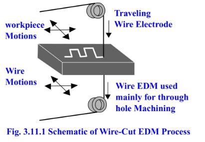
In the wire-cut EDM process, water is commonly used as the dielectric fluid. Filters and de-ionizing units are used for controlling the resistivity and other electrical properties. Wires made of brass are generally preferred. The water helps in flushing away the debris from the cutting zone. The flushing also helps to determine the feed rates to be given for different thickness of the materials. The schematic of wire cut EDM is shown in Figure 3.2.6.
The WEDM process requires lesser cutting forces in material removal; hence it is generally used when lower residual stresses in the workpiece are desired. If the energy/power per pulse is relatively low (as in finishing operations), little changes in the mechanical properties of the material are expected due to these low residual stresses. The materials which are not stress-relieved earlier can get distorted in the machining process. The selection of process parameters is very crucial, as in some cases the workpiece undergoes significant thermal cycles that can be very severe. These thermal cycles can form recast layers and induce residual tensile stresses on the workpiece which are undesired.
Process of Material Removal in Wire-Cut EDM
In the WEDM process, the motion of wire is slow. It is fed in the programmed path and material is cut/ removed from the workpiece accordingly. Electrically conductive materials are cut by the WEDM process by the electro-thermal mechanisms. Material removal takes place by a series of discrete discharges between the wire electrode and workpiece in the presence of a di-electric fluid. The di-electric fluid gets ionized in between the tool-electrode gap thereby creating a path for each discharge. The area wherein discharge takes place gets heated to very high temperatures such that the surface gets melted and removed. The cut particles (debris) get flushed away by the continuously flowing dielectric fluid.
WEDM is a non-conventional process and is very widely used in tool steels for pattern and die making industries. The process is also used for cutting intricate shapes in components used for the electric and aerospace industries.
Applications of Wire-Cut EDM
Wire EDM is used for cutting aluminium, brass, copper, carbides, graphite, steels and titanium. The wire material varies with the application requirements. Example: for quicker cutting action, zinc-coated brass wires are used while for more accurate applications, molybdenum wires are used.
The process is used in the following areas:
Aerospace, Medical, Electronics and Semiconductor applications
Tool & Die making industries.
For cutting the hard Extrusion Dies
In making Fixtures, Gauges & Cams
Cutting of Gears, Strippers, Punches and Dies
Manufacturing hard Electrodes.
Manufacturing micro-tooling for Micro-EDM, Micro-USM and such other micro-machining applications.
Last modified: Tuesday, 29 April 2014, 9:14 AM