Site pages
Current course
Participants
General
MODULE 1. Analysis of Statically Determinate Beams
MODULE 2. Analysis of Statically Indeterminate Beams
MODULE 3. Columns and Struts
MODULE 4. Riveted and Welded Connections
MODULE 5. Stability Analysis of Gravity Dams
Keywords
LESSON 32. Stability Analysis of Gravity Dams: Profile
The economy and safety of a gravity dam depend on many geometric parameters such as height of the dam, crest height, base width, upstream and downstream slopes etc. Therefore, an optimum shape design is an important problem in dam engineering. Determination of the optimum shape of a gravity dam involves several iterations and modifications. It is always better to start with an elementary profile and then do the necessary modification depending on the loading conditions, geometric feasibility etc. In this lesson we will learn how to fix an elementary profile of a gravity dam.
32.1 Elementary Profile
While determining the elementary profile of a gravity dam only pressure due to water is considered. Therefore the dam is subjected to horizontal water pressure at the upstream face and uplift pressure at the base. In such case a right angled triangular profile as shown in Figure 32.1, provides the maximum possible stabilizing force against overturning, without causing tension in the base. This profile is defined by two parameters viz, dam height (H) and base width (b). The procedure to determine the dam height and base width is given bellow.
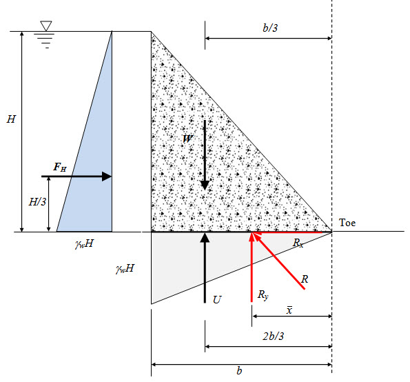
Fig. 32.1.
32.1.1 Base width of elementary profile
First the required base width is determined based on two criteria; (i) no sliding stress criteria and (ii) no tension criteria. The greater of the width given by the both criteria is taken as the width of the elementary profile.
(a) No sliding criteria
Horizontal force due to water pressure should be balanced by the frictional resistance. Therefore condition for no sliding is,
\[{F_H}=\mu \left( {W - U} \right)\] (32.1)
\[\Rightarrow {1 \over 2}{\gamma _w}{H^2}=\mu \left( {{1 \over 2}{\gamma _C}bH - {1 \over 2}{\gamma _w}bH} \right)\] (32.2)
\[\Rightarrow b=\frac{{{\gamma _w}H}}{{\mu\left({{\gamma _C}-{\gamma _w}}\right)}}=\frac{H}{{\mu\left({\frac{{{\gamma _C}}}{{{\gamma _w}}}-1}\right)}}\Rightarrow b=\frac{H}{{\mu \left({{S_c}-1}\right)}}\]....(32.3)
\[{S_c}={{{\gamma _c}}{\left/{{{\gamma _c}} {{\gamma _w}}}} {{\gamma _w}}}\] specific gravity of dam material ]
If uplift is neglected, \[b={H{\left/ {{H {\mu {S_c}}}}}{\mu {S_c}}}\]
In this case the normal stress developed at the base of the gravity dam varies as linearly with maximum tensile stress at the heel and maximum compressive stress at the toe as shown in Figure 32.3.
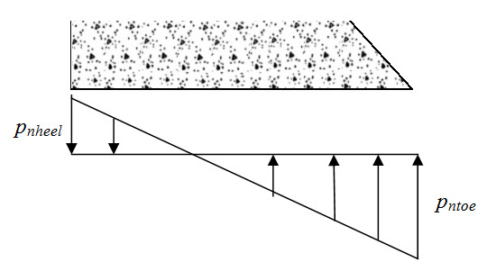
Fig. 32.2.
\[{p_{ntoe}}\] and \[{p_{nheel}}\] are given by,
\[{p_{ntoe}}={{{R_y}} \over b}\left( {1 + {{6e} \over b}} \right)\] (32.4)
\[{p_{nheel}}={{{R_y}} \over b}\left( {1 - {{6e} \over b}} \right)\] (32.5)
where, \[e={b \over 2} - {{{M_{toe}}} \over {{R_y}}}\] (32.6)
Now,
\[{R_y}=W - U = {1 \over 2}{\gamma _w}bH\left( {{S_c} - 1} \right)\] (32.7)
\[{M_{toe}}=W{{2b} \over 3} - {F_H}{H \over 3} - U{{2b} \over 3}={{{b^2}} \over 3}{\gamma _w}H\left( {{S_c} - 1} \right) - {{{H^3}} \over 6}{\gamma _w}\] (32.8)
From Equations (3) and (6) – (8), we have,
\[{p_{ntoe}}={\gamma _w}H{\mu ^2}{\left( {{S_c} - 1} \right)^2}\] (32.9)
\[{p_{ntoe}}={\gamma _w}H\left( {{S_c} - 1} \right)\left[ {1 - {\mu ^2}\left( {{S_c} - 1} \right)} \right]\] (32.10)
Corresponding principal stress at toe,
\[{\sigma _1}={p_{ntoe}}{\sec ^2}\varphi\] (32.11)
\[\Rightarrow {\sigma _1}={\gamma _w}H{\mu ^2}{\left( {{S_c} - 1} \right)^2}\left[ {{{\left( {b/H} \right)}^2} + 1} \right]\] [ \[\tan \varphi=b/H\] ] (32.12)
\[\Rightarrow {\sigma _1}={\gamma _w}H\left[ {{\mu ^2}{{\left( {{S_c} - 1} \right)}^2} + 1} \right]\] [ \[b={H \over {\mu \left( {{S_c} - 1} \right)}}\] ] (32.13)
Similarly, shear stress is,
\[\tau={\gamma _w}H{\mu ^2}{\left({{S_c}-1} \right)^2}\tan \varphi\Rightarrow\tau={\gamma _w}H\mu \left( {{S_c}-1} \right)\] (32.14)
Following the similar approach stresses at the heel can be computed.
No tension criteria
Tension generally occurs at the heel. Condition for no tension is,
Moment of FH about heel = moment of Ry about heel.
\[\Rightarrow {F_H}{H \over 3}=\left( {W - U} \right){b \over 3}\] (32.15)
\[\Rightarrow {1 \over 6}{\gamma _w}{H^3}=\left( {{1 \over 2}{\gamma _C}bH - {1 \over 2}{\gamma _w}bH} \right){b \over 3}\] (32.16)
\[\Rightarrow {H^2}=\left( {{S_C} - 1} \right){b^2}\] (32.17)
\[\Rightarrow b={H{\left/ {\sqrt {\left( {{S_C} - 1} \right)} }}\] (32.18)
If uplift is neglected, \[b = {H{\left/ {\sqrt {{S_c}} }}\].
In this case the normal stress developed at the base of the gravity dam varies linearly with zero value at the heel and maximum at the toe as shown in Figure 32.3.
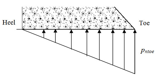
Fig. 32.3.
\[{1 \over 2}b{p_{ntoe}}=W - U \Rightarrow {1 \over 2}b{p_{ntoe}}={1 \over 2}{\gamma _C}bH - {1 \over 2}{\gamma _w}bH\] (32.19)
\[\Rightarrow {p_{ntoe}}={\gamma _w}H\left( {{{{\gamma _C}} \over {{\gamma _w}}} - 1} \right) \Rightarrow {p_{ntoe}}={\gamma _w}H\left( {{S_c} - 1} \right)\] (32.20)
Corresponding principal stress at toe,
\[{\sigma _1}={p_{ntoe}}{\sec ^2}\varphi\] (32.21)
\[\Rightarrow {\sigma _1}={\gamma _w}H\left( {{S_c} - 1} \right)\left[ {{{\left( {b/H} \right)}^2} + 1} \right]\] [ \[\tan \varphi=b/H\] ] (32.22)
\[\Rightarrow {\sigma _1}={\gamma _w}H\left( {{S_c} - 1} \right)\left[ {{1 \over {{S_C} - 1}} + 1} \right]\] (32.23)
\[\Rightarrow {\sigma _1}={\gamma _w}H{S_c}\] (32.24)
Similarly, shear stress is,
\[\tau={p_{ntoe}}\tan\varphi\Rightarrow\tau={\gamma _w}H\left( {{S_c} - 1} \right){b \over H} \Rightarrow \tau={\gamma _w}H{{\left( {{S_c} - 1} \right)} \over {\sqrt {\left( {{S_c} - 1} \right)} }}\] (32.25)
\[\Rightarrow \tau={\gamma _w}H\sqrt {\left( {{S_c} - 1} \right)}\] (32.26)
32.1.2 Limiting height of a gravity dam
The limiting height of a gravity dam is determined based on no tension criteria. The maximum value of principal stress should not exceed the permissible value.
Therefore,
\[{\sigma _1}\le{\sigma _a}\] [ \[{\sigma _a}\] is the allowable normal stress]
\[\Rightarrow {\gamma _w}{H_{\lim }}{S_c} \le {\sigma _a}\]
\[\Rightarrow {H_{\lim }} \le {{{\sigma _a}} \over {{\gamma _w}{S_c}}}\] (32.27)
Generally, uplift pressure is not considered while determining the limiting height of a gravity dam. Following the approach given in section 32.1.1, it can be shown that for no uplift pressure Equation (27) is reduced to,
\[{H_{\lim }} \le {{{\sigma _a}} \over {{\gamma _w}\left( {{S_c} + 1} \right)}}\] (32.28)
Suggested Readings
Garg, S.K. Irrigation Engineering and Hydraulic Structures. Khanna Pub.
Last modified: Saturday, 21 September 2013, 11:25 AM