Site pages
Current course
Participants
General
MODULE 1. Planning of Farmstead
MODULE 2. Physiological Reactions of Livestock
MODULE 3. BIS Standards
MODULE 4. Farm Structures
MODULE 5.
MODULE 6. Rural Living and Development
MODULE 7. Water Supply
Topic 8
Topic 9
Topic 10
LESSON 18. Water treatment suitable to rural community
The various methods which may be adopted for purifying the public water supplies are,
(i) Screening
(ii) Plain Sedimentation
(iii) Sedimentation aided with Coagulation
(iv) Filtration
(v) Disinfection
(vi) Aeration
(vii) Softening
(viii) Miscellaneous treatments such as fluoridation, recarbonation, liming, desalination etc.
Among the above processes screening, plain sedimentation and filtration are suitable to rural community
Screening : Screens are generally provided in front of the pumps or intake works
They remove the large sized particles like debris, branches, bushes, ice etc.
Coarse and fine screens may be provided. Coarse screens are parallel iron rods which are placed vertically or at an angle to the horizontal at 30º – 60º at 2-10 cm centre to centre. Fine screens are made of fine wires or perforated metal with openings less than 1 cm wide. The velocity through the screen should not be more than 0.8 to 1 m/sec.
Plain Sedimentation : Most of the suspended impurities present in water have a specific gravity more than that of water (1.0). These impurities will remain in suspension in flowing water (turbulence). If the water is made to stand still, the impurities will settle down under gravity. Hence, if the turbulence is retarded, i.e. if the water is made to stand still or stored, these impurities tend to settle down at the bottom of the tank. This is the principle behind sedimentation. The basin in which the flow of water is retarded is called settling tank or sedimentation tank or sedimentation basin or clarifier. The theoretical average time for which the water is detained in the tank is called the detention period.
Sedimentation tank :
They are made of RCC structure and may be either rectangular or circular
|
Rectangular tank |
Circular tank |
|
Long narrow rectangular tanks with horizontal flow |
Circular tanks with radial or spiral flow |
Also they may function intermittently or continuously.
|
Intermittent Function |
Continuous Function |
|
Simple settling basin keeps the raw water for certain periods at rest. After @ 24 hrs, the clear water is drained off & the tank is cleaned to remove the settled silt |
Here only the flow velocity is decreased water is not brought to complete rest. Here water enters from one end and comes out from other end. |
Design of Continuous Flow Type Sedimentation Tank
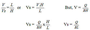
It is assumed that the sediment is uniformly distributed as the water enters the basin. If q is the discharge entering the basin, with a uniform flow velocity V, then V is given by
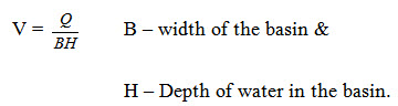
Let the sediment particle move with a horizontal velocity V and a downward vertical velocity Vs. The resultant path of the particle is given by the vector sum of its flow velocity V and settling velocity Vs.
Now By geometric considerations
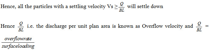
Its value for plain sedimentation tank is 500 – 750 lit/hr./m2 and for coagulation sedimentation tank is 1000 – 1250 lit/hr./m2 of plan area.
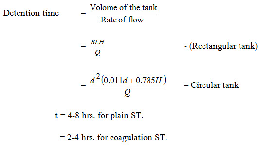
Depth of water ranges between 1.8 m to 6 m. Usually it can be taken as 3.0 to 4.5m. Detention period is the average theoretical time for which the water is detained in the tank (or) is the average theoretical time required for the water to flow through the tank.
- Width of the tank B ranges between 10 m & 12 m.
- Length of the tank is not allowed to exceed 4 times width.
- Maximum limit is L should not be more than 1 – 6 times width.
- Horizontal flow velocity V ranges between 0.15 – 0.9m/min. & it is normally = 0.3 m/min.
- Total amount of flow from the tank within 24 hrs is equal to the maximum daily demand of water.
Flowing through period: It is the actual average time taken by the water to pass through a settling tank. This will be the case when there is a short circuiting. i.e. passing of a substantial portion of water directly through the tank without being detained for the intended time. The ratio of flow through period to detention period is called the displacement efficiency.
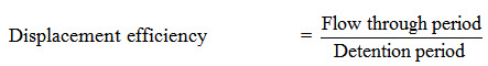
It generally varies between 0.25 to 0.50
By sedimentation tank, 70% of suspended impurities is removed.
Problem: A circular sedimentation tank fitted with standard mechanical sludge removal equipment is to handle 3.5 million litres per day of raw water. If the detention period of the tank is 5 hours, and the depth of the tank is 3 m, what should be the diameter of the tank?
Quantity of raw water to be treated per day = 3.5 x 10⁶ lit.
Quantity of water to be treated during detention period = Capacity of the tank
= 3.5 x 10⁶ 5/24
= 728 x 103 lit.
= 728 cu. m. –------- (1)
The capacity of a circular tank of depth H & dia d is given by =
= d2(0.011 d + 0.785 H)
= d2(0.011 d + 0.785x3) – (2)
Equating (1) + (2), d2(0.011d + 0.785 x 3) = 728
RHS = 2465
By trial and error, d = 20, RHS = 1030
d = 15, RHS = 507
d = 17, RHS = 734.64
d = 16.8, RHS = 716.83
d = 16.9m, RHS = 725.71
Filtration
The water after the treatment of screening, sedimentation & coagulation sedimentation also may contain very fine suspended particles and bacteria in it. In order to remove the remaining impurities, the water is passed through the beds of fine granular material like sand etc. The process of passing the water through beds of granular materials is known as filtration. Filtration helps in removing colour, odour, turbidity & Pathogenic bacteria from water.
Filter materials :
Either fine sand or coarse sand is used as filter media. The layers of sand is supported on gravel and this layer permits the filtered water to move freely to the bottom.
Sand :
The filter sand should be obtained from rocks like quartzite & should be (i) free from dirt & other impurities (ii) uniform in nature & size (iii) hard and resistant (iv) should not loose greater than 5% of its weight after being placed in HCl for 24 hours. Effective size i.e D10 is defined as the size of sieve in mm through which 10% of the sample of sand by weight will pass through. Uniformity coefficient D60/D10 is defined as the ratio of the sieve size in mm through which 60% of the sample will pass to the effective size of sand.
Gravel :
The gravel which is used below the sand should be hard, durable, free from impurities, properly rounded and should have a density of @ 1600km/m3.
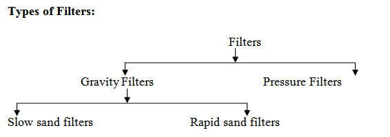
Slow sand filters :
The various parts of this filter are discussed below.
(i) Enclosure tank :
It is an open water tight rectangular tank made of masonry or concrete. The bed slope is 1 in 100 towards central drain. Depth varies between 2.5 and 3.5 cm and the plan area is 100 - 2000 m2.
(ii) Filter Media :
A sand layer of 90-110 cm depth is used. It is placed over a gravel support. The effective size of sand, D10 is 0.2 to 0.4 mm. Uniformity coefficient (D60/D10) varies from 1.8 to 2.5. Finer variety of sand should be kept at the top. If different grades of sand are used then coarse layer is kept near the bottom and the finest towards the top. The finer the sand used, the purer will be the obtained water.
(iii) Base Material:
It is gravel & it supports the sand. It depth varies between 30-75 cm.
(iv) Under drainage system:
The gravel support is laid on the top of an under drainage system. It contains central drain and lateral drain. Lateral drains are open jointed pipe drains or porous pipes and they are placed 3.5 cm apart.
(v) Inlet & outlet arrangements:
Inlet chamber is provided which admits water without disturbing the sand layers of the filter. A filtered water well acts as outlet. To maintain a constant discharge through the filter, an adjustable telescopic tube is generally used.
Operation:
The influent water enters the inlet chamber & gets distributed uniformly over the filter bed. The water passes through the filter media & gets purified. Then, it passes through the gravel and gets collected in laterals through open joints and discharges into filtered water well. The depth of water on the filter media should not be too large or too small. Depth of water is equal to depth of filter sand
Filter head: When water passes through the sand, gravel etc. there will be loss of head which is caused by the resistance offered by the sand grains to the flow of water. This loss of head is called filter head or filtering head. Filter head is the difference of water level in the filter tank and the filtered water well. Generally filter head is more than 0.7 to 1.2 m. But if filter head reaches a value nearer to this limit, the filter unit should be cleaned.
Cleaning:
It is done by scrapping & removing the 1.5 to 3 cm of top sand layer. The top surface is then cleaned & washed with good water. The quantity of water required is in the order of 0.2-0.6% of total water filtered. Cleaning can be done up to a depth of 40 cm. Then more sand is added. After each cleaning, the filter can be used & the effluents are used only after 24 to36 hours. Rate of filtration or rate of loading should be at the rate of 100-200 lit./ml. of plan area.
Efficiency:
The extent of bacteria removal is up to 98-99%
Problem: Design six slow sand filter beds from the following data :
Population to be served - 50,000 persons
Per Capita demand - 150 lit/head/day
Rate of filtration - 180 lit/head/sq.m.
Length of each bed - 2 x breadth
Assume maximum demand as 1.8 times the average daily demand.
Also, assume that one unit, out of six, will be kept as stand by.
Rapid Sand Filters:
These filters employ coarse sand, with effective size as 0.5 mm or so. Yield by this filter is 30 times that of slow sand filter. Water from coagulation sedimentation tank is used in these filters.
Construction:
Enclosure tank : Open water tight rectangular tank made of masonry or concrete is used. Depth is varied from 2.5 to 3.5m. Area of filter unit is 10 to 80 m2. N = 1.22 ÖQ where Q - Plant capacity in Ml/d and N – Number of filters.
Filter Media : A sand layer of 60-90 cm depth is used over gravel support. Effective size D10 of sand is 0.35 to 0.55 m and uniformity coefficient D60/D10 is 1.2-1.8.
Base Material : It supports the sand and also distributes the wash water. Depth is 60-90 cm and arranged in 4 to 6 layers. Critical function of the gravel layer is the distribution of wash water.
Under – drainage system : In slow sand filters, the under drainage system was provided only to receive and deliver the filtered water, whereas, in rapid gravity filters, the under drainage system serves two purposes : viz (i) to receive and collect the filtered water, and (ii) to allow the back washing for cleaning of filter. In addition to collecting the filtered water during its downward journey it should be capable of passing the wash water upward at a high rate of 300-900 lit/min/sq.m. of floor area. Since the rate of application of wash water is greater than the rate of filtration (6-16 time) (50-100 lit/min/m2) the design of under drainage system should be done in such a way that there is even and uniform distribution of wash water. Forms of under drainage systems are
(i) Manifold & lateral system.
(ii) Wheeler bottom
(iii) Porous plate bottom etc.
Manifold & lateral system:The laterals may be either (i) Perforated Pipe type system and
(i) Perforated Pipe type system :The lateral drains are provided with holes at the bottom side. The holes are 6-13 cm in diameter & make an angle of 300 with vertical. Brass bushings are inserted in these holes to avoid the rusting of the surfaces of the holes. Laterals are supported over 40-50mm thick concrete blocky which are placed on the floor of the filter.
(ii) Pipe & Strainer type : Here, holes are not drilled into the laterals. But strainers are placed on the lateral drains. A strainer is a small brass pipe closed at its top by a perforated cap.
Factors to be considered during designing the sizes of pipes to be used in the above system are
- The total cross-sectional area of perforations should be @ 0.2% the total filter area.
- Cross-sectional area of each lateral = 2 - 4 times the total cross-sectional area of perforations for 13 mm to 6 mm diameter lateral.
- Cross-sectional area of the manifold central drain = 2 x cross-sectional area of laterals.
- Length of each lateral/Diameter of the lateral should not be more than 60.
- Maximum permissible velocity in manifold to provide required amount of wash water = 1.8 – 2.4 m/sec.
Other appurtenances:
(i) Wash water troughs : The dirty wash water which comes out of the filter after cleaning it, is collected in wash water troughs / gutters and carried to the main gutter. These gutters may be square, V-Shaped or semi-circular. They may be of cast iron, concrete, steel or wrought iron. The troughs are usually spaced at @ 1.5 – 2.0 m apart.
(ii) Air compressor : During back washing the filter, the sand grains are agitated either by water jet or by compressed air or by mechanical rates. When compressed air is used, air compressor unit having the required capacity, must be installed. The compressor should supply compressed air for about 4 minutes at a rate of about 600-800 lit/min/m2.
(iii) Rate controller : In order to automatically obtain a uniform rate of filtration irrespective of the head loss through the filter, rate controllers are required to be fitted at the outlet end of each filter unit.
(iv) Head loss indicator:
It is a differential type of a mercury gauge, one end of which is connected to the water resting on the sand bed and the other end to the effluents coming from the filter.
Working and Cleaning Operation:
Filtering:
Valve (1) is opened – water enters the inlet clumber & the filter.
Valve (4) is opened after filtering, and the filtered water is taken out.
Back Washing : When sand becomes dirty, (indicated by excessive loss of head) the filter must be cleaned & washed. For this purpose, wash water is sent bach upward through the filter beds. This forced upward movement of wash water & compressed air, will agitate the sand particles & removes the suspended impurities from it. Valves (1) & (4) are closed. Valves (5) & (6) are opened. Wash water & compressed air are forced upward from the under drainage. Valve (5) is closed after supplying the required amount of air. The dirty water resulting from washing over flows into the wash water troughs. Valve (2) is opened & the dirty water is removed into the wash water gutter. Washing is done for 3-5 minutes. After the washing is completed, valves (2) & (3) will be closed and valves (1) & (3) are opened out. The filtered water is not collected & washed for a few minutes through valve (3) to the gutter.
Then (3) is closed & (4) is opened.
Design of Slow Sand Filters
- Design six slow sand filter beds from the following data :
Population to be served = 50,000
Per capital demand = 150 lit/head/day
Rate of filtration = 180 lit/head/sq.m.
Length of each bed = Twice the breadth
Assume maximum demand as 1.8 times the average daily demand. Also assume that one unit, out of six will be kept as stand by.
- Design slow sand filter for the following data.
Population = 1 lakh
Per capacity demand = 140 lit/day
Total Maximum demand = 1.5 times average
Indicate general arrangement of filter beds.
- Design six slow sand filter beds from the following data & show the arrangements of bed in plan.
Pop. to be served = 75,000
Quality of water to be supplied = 200 lit./head/day
Fate of filteration = 300 lit/sq.m./day
Length of each bed is twice the breadth
Last modified: Friday, 7 February 2014, 11:38 AM