Site pages
Current course
Participants
General
Module 1. Introduction to human engineering
Module 2. Human performance and responses
Module 3. Working environment and work space design
Module 4. Rehabilitation scheme and DMR Act
Topic 5
Topic 6
Topic 7
Topic 8
Topic 9
Topic 10
Lesson 9. HUMAN MOTOR ACTIVITIES, CONTROLS, TOOLS AND RELATED DEVICES
9.1 Human motor activities
Human activities that fall within optimum level of intensity i.e. mental psychomotor and physical activities. The intensity of work activity increased with the increase in likelihood of boredom, i.e. mental to physical. The nature of human physical responses and activities have implications for many aspects of human factor, viz. the design of control devices, hand tools and other devices, handling of materials, physical layout and arrangement of workspace methods and procedures.
The immediate output of human activity is most job situations include the execution of physical responses or communications, which accomplish some desire objectives. The ability of operation to perform various types of motor activities depends upon the physical structure of the body, the skeletal muscle, nervous system and the metabolic processes.
9.1.1. Physical Skeletal Structure:
The physical structure of the body consists of Skelton formed by 206 bones. These bone structures serves the purpose of housing and protecting the essential organs (skull and ribcage) of the body. The skull protects the brain and ribcage protects the lungs, heart, and other internal organs. The upper and lower extremist and the articulated bones of the spine are concerned primarily with the execution of physical activities.
9.1.2. Skeletal Muscle structure:
The skeletal muscle consists of bundles of muscle fibres which seems to convert chemical energy in to mechanical work. The bones of the body are held together at their joints by ligaments. The two end of each muscle blend in to tendons, which intern are connected to different skeletal bones in such a manner that due to activation of muscles, some form of mechanical leverages applied.
9.1.3. Neural Control activity of muscles:
Neural control of muscle activities can be controlled by sensory nerves and motor nerves, which has already been discussed in section 8.5.2.
9.1.4. Muscle metabolism:
It is the collective chemical process of conversion of food stuffs into two forms, i.e. mechanical work and heat work. Some of the mechanical work is used externally as in physical tasks. Usually heat is generated in surplus amounts, which must be dissipated by the body. The contraction of muscle require energy which is formed by glycogens. The conversion of glycogens in to energy consists of a chemical reaction, that ends in the production of lactic acid. At the initiation of physical activity the muscle can utilize the glycogen in to energy.
When an adequate amount of oxygen is supplied, the accumulation of lactic acid is very little. If the activity level requires more oxygen then is provided by the normal blood flow rate through cardiovascular system. The increased demands adjusted by the system. This increased demand is adjusted by increasing the heart rate to pump more blood through cardiovascular system. The blood is pumped from the heart through the lungs, where it picks up a supply of oxygen, which is then carted by the blood to the muscle where oxygen is needed. At moderate rate of work activity, the heart rate and breathing rate are normally increased to the level that provides enough oxygen to perform the physical activities over a continuing period of time. At thigh rate of work activity, when the amount of oxygen delivered to the muscle fails to meet the requirements, lactic acid tends to accumulate in the blood. At continued duration of physical activity the muscle will ultimately cease to respond.
9.2 Control:
A control is a device that enables an operator to change the state of a mechanism. It convert the output of an operator into the input of a machine controls are pieces of hardware and are after regarded as parts of a machine but for design purpose they can be considered as links between the machine & the operator. A control transmits the information from the man to the machine and the starting point of design must be the output character ties of the operator.
Output devices of an operator:–
i) Four limbs (two hands & two feet)
ii) Voice (man to man vocal output is useful but for man & machine it is of no use.
Basic output of human limb is force: so the controls can be in the form of Pressure control and Displacement control.
9.2.1 Pressure control: is one that effectively does not move at all, but the force or torque exerted on it influences the machine.
9.2.2 Displacement control: is the one for which the change of state of the machine is a function of the distance or angel through which the control has been moved. The direct feedback from displacement controls is much more complex, since it depends upon the control restoring forces. They may not exist, in which case the control stays wherever it is put and feedback is a matter of sensing displacement.
The key feature of control as a function of applied force to be used effectively without vision. For this it is often useful to provide mechanical gates through which controls move and which provides pressure & displacement cues, which is turn enables the operator to know what he has done without looking at the control. This has been achieved in gear levers for motor cars and operation of such well designed control mechanisms is a source of pleasure for operator. This is regardless of which limbs, tomb and muscles are involved in control activation.
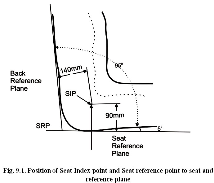
Seat Index Point (SIP):
The seat index point is the interaction on the central vertical plane passing through the seat centre line of the theoretical pivot axis between a human torso and thighs.
Seat Reference Point (SRP):
The seat reference point is the point in the central longitudinal plane of the seat where the tangential plane of the lower backrest and a horizontal plane intersect. The SIP is located 90 mm above and 140 mm in front of SRP (Fig.9.1).
9.2.3 Placement of the controls in optimum areas
The concept of optimum dimensions and limiting dimension is used in the placement of controls in space and it applies to both manual and pedal areas. The optimum dimensions define the most desirable space for the location of controls both in their neutral position and when displayed in any direction. This is an ideal’ area reserved primary for the most important controls together with those which are used frequently. The limiting dimensions define the acceptable but not the most desirable space or the location of controls. If controls are placed outside the space, they are neither too close nor too far from the operator. The dimensions usually chosen to define the boundaries of these spaces are estimated to cater for 90% of the operator population that is from the 5th to the 95th percentiles.
Two types or controls namely operated by hand and foot are considered. Foot control are best for provision of powerful or continuous forces and hand controls are used for speed and precision. A maximum of 4 foot controls can be operated by an operator in the absence of highest degree of practise and skill. Assuming that the operator is seated and can maintain equilibrium without relying on his feet. Standing operator cannot use foot controls without extensive postural adaptation. Because it is uneconomic in speed & energy expenditure wide individual differences in the ability to coordinate hand and foot control movements.
9.2.4 Grouping of control location and actuating forces
While arranging the controls within the work place area, three major factors i.e. priority, grouping and association should be considered. Priority depends on the frequency and extent of use. The highest priority controls should be place within the optimum spaces. Emergency controls must be placed in readily accessible positions. Secondary controls should be placed within the limiting areas but not necessarily in the optimum area. Setups and calibration controls, which are used infrequently, may be located outside the operator’s normal work space.
Grouping may be done generally by functional and sequential grouping. In functional grouping all controls, which are identical in function (eg. Light switches) or used together in a specific task (e.g. position and draft control) are grouped together. In sequential grouping controls are grouped and arranged in normal order of use.
Control location and actuating forces
Hand controls
Hand controls should be used in preference to foot control where (i) accuracy of control positioning is important. The hand and arms are much more accurate than feet and speed of control positioning is required. (ii) Continuous or prolonged application of moderate or large forces (20 ibf, 89N or more).
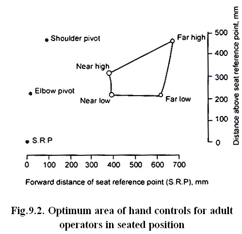
The seated position is preferable to the standing position especially if the controls are to be operated for any length of line. Standing is more fatiguing and usually results in less efficient, weaker or less accurate control of movements. One hand controls are preferable to those operated with hands, for precision and speed, except that large diameter control wheels with reciprocating motion (steering wheels) are operated with two hands. Where larger forces are required, and operation controls are to be used. The preferred hand – be used where speed, accuracy or strength of the control movement are important. The recommended dimension for the optimum manual control of male operators is about 24’’ (600 mm) wide, 12’’ (300 mm) either ride of the midline. The Fig. 9.2. shows the optimum with respect to a horizontal seat cushion and is valid for a – seated with back vertical.
Then all the controls cannot be placed within the optimum location immediately adjacent to the optimum control areas more desirable than those dimensions than those farther away. Normally the dimensions of the controls placement are given w.r.t seat reference point. For those dimensions to be applicable in all the reference point should be adjustable at least 125 mm horizontally and 125 mm vertically.
The variety of hand controls is commensurate with the versatility of the hands. Steering wheel is the hand equivalent of the rudder-bar and has the corresponding advantage of achieving precision by balancing forces between the two hands. It makes possible a wide variety of position & type of grip (hand grip) and operation by either hand or by both hands and can also provide a large torque.
Ideally the optimum vertical location of controls for the standing operator would tie between the shoulder level and the elbow level with the arms at the side of the body. If this area is to be optimised both tall and short operators (lower limit at height of small operator), the residual area would be too small to be practical value. The best alternate is to use the dimensions of the average (50th percentile) operator.
Table.9.1. Maximum operating forces required for operating tractor controls
|
S. No. |
Devices to be operated |
Type of control |
Maximum actuating force to operate control (N) |
|
1 |
Service brake |
Pedal Hand lever |
600 400 |
|
2 |
Parking brake |
Pedal/ Hand lever |
600 400 |
|
3 |
Clutch |
Pedal |
350 |
|
4 |
PTO coupling |
Pedal/ Hand lever |
300 200 |
|
5 |
Manual Steering system |
Steering Wheel |
250 |
|
6 |
Hydraulic power lift system |
Hand lever |
70 |
Foot controls
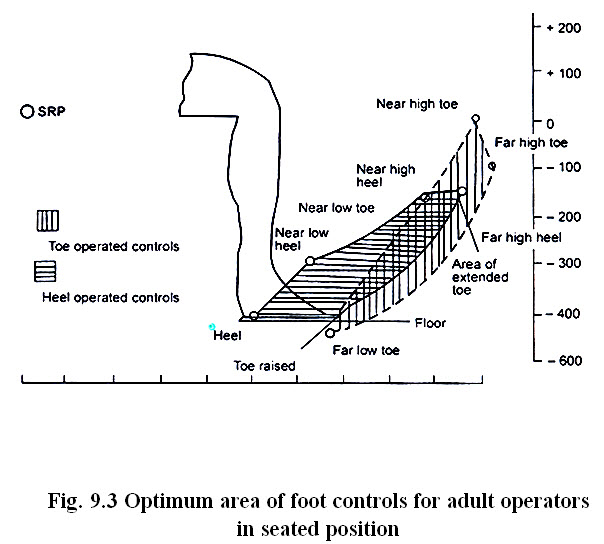
Foot controls are to be used in preference to hand controls where, i) there is a continuous control task in which precision or control positioning is not of primary importance, ii) the application of moderate to large forces greater than 20- Ibf (89-199n) is necessary intermittently or continuously, iii) the hands are in danger of being overburdened with control tasks. Pedals may be divided into two groups: those designed for use when the force is above 10-20 Ibf (44-89N) and is obtained by movement of the leg (brake pedals) and those where the force is obtained primarily from the ankle (e.g. an accelerator pedal) which should be used where small forces of about 10 Ibf (44N) or less & continuous operation is required (Table.9.1). The long axes of the foot and lower leg should the foot in position. The optimum pedal area which is most desirable for the location of the foot controls both in their natural position and when displaced in my direction in shown in Fig 9.3. In locating foot controls for the seated position within these optimum areas, there are three considerations: the locations fore & aft location, the vertical location and the lateral locations. Fore & aft seat reference point to pedal distance is an important determinant of the amount of pressure exorable on the foot control. The shorter the distance, than the force exertable, pedals can be placed below the S.R.P. by vertical distances varying with the type of task. As pedals are moved laterally from midline of the leg, the force exertable.
Foot controls should be designed to be operated from the created position. For the seated position, a backrest should always be provided. There is little difference between the legs with regard to strength, speed or accuracy but most people prefer the right leg especially for critical tasks. Common foot controls are pedal, rotating pedal, beadle, rudder bar and rotating platform. Pedal design is largely an anthropometric problem of placement in relation to the floor and seat. It is essential to have adjustable seat. Pedal should be provided with 1.non-slip surface 2. Restoring force should be large enough to support to the weight of the foot. Rotating peddle & treadle are really relics of the times when it was necessary to provide rotation by reciprocal foot activity e.g sewing machines and potter’s wheels. Rotating platform is particularly useful for adjusting the orientation of machine or material in relation to the operator’s hands.
Brake pedal : Operating a brake or clutch pedal of a tractor requires the driver to exert a force so as to move the pedal at prescribed distance along its axis of travel. The first requirement for accident prevention is that brakes operate quickly and easily, therefore it is greatest convenience for the operator results from locating the brake pedal directly in front of the normal foot position.
Clutch pedal : the clutch pedal is used very frequently even more frequently than the brake pedals. Therefore it is necessary for the operation of clutch pedal is usually smaller than that required for brake pedals. Therefore it should be located in a position symmetrical with the brake pedal, with the centre axis of driver serving as the symmetrical axis for both.
Accelerator pedal: control of engine speed by means of a foot accelerator is easier than by hand throttle lever, because the hand is required for steering, gear shifting lever, operating hydraulic controls and engaging parking brakes. The ankle joint is particular suited to sense a position and maintain close regulation; 200 movement of the ankle affords a sufficient degree of accuracy. In addition to the magnitude of pedal motion, the force necessary to operate the pedal is of great significance for accurate regulation of engine speed. If pedal pressure is too high, the energy required to continuously operate the pedal will be excessive.
9.6 Tools and related devices
Probable there are couple of interrelated consideration dominant in the design or selection of many hand tools, equipments that are used in various domestic, agricultural and industrial operations, i.e khurpa, sickle, kasola etc. Certainly these tools and devices need to be capable of performing their function, such as digging soil, cutting crops etc. The mechanization revolution brought about the use of machines for doing such operations. The invent of machine typically required that people exercise control, controls by some control by hand or foot control mechanism.
Last modified: Saturday, 1 February 2014, 5:00 AM