Site pages
Current course
Participants
General
Module 1: Basics of Agricultural Drainage
Module 2: Surface and Subsurface Drainage Systems
Module 3: Subsurface Flow to Drains and Drainage E...
Module 4: Construction of Pipe Drainage Systems
Module 5: Drainage for Salt Control
Module 6: Economics of Drainage
Keywords
Lesson 3 Design of Surface Drainage Systems
3.1 Introduction
Drainage can be either natural or artificial. Natural drainage is often inadequate, and hence artificial (man-made) drainage is required. There are two types of artificial drainage: surface drainage and subsurface drainage (FAO, 1985). Broadly speaking, surface drainage is the removal of excess water from the surface of the land. It is the oldest drainage practice and is defined as (ICID, 1982):
“The diversion or orderly removal of excess water from the surface of land by means of improved natural or constructed channels, supplemented when necessary by shaping and grading of the land surface to such channels”.
As mentioned in Lesson 2, surface drainage is applied primarily on flat lands where slow infiltration, low permeability, or restricting layers in the profile prevent the ready absorption of high-intensity rainfall. Therefore, this drainage system is intended to eliminate ponding and prevent prolonged saturation by accelerating flow to an outlet without causing soil erosion or siltation. Two primary methods of surface drainage are land grading and field ditches. The selection of surface drainage facilities for individual field areas depends largely on the topography, soil characteristics, crops, and availability of suitable outlets. Note that surface drainage may be required even though subsurface drains are installed.
3.2 Components of Surface Drainage System
The negative effects of poor surface drainage on agricultural productivity can be summarized as follows:
Inundation of crops, resulting in deficient growth.
Lack of oxygen in the root zone, hampering germination and the uptake of nutrients.
Insufficient accessibility of the land for mechanized farming operations.
Low soil temperature in spring time (applicable to temperate regions).
To improve the growing conditions of crops in the field by ensuring the timely and systematic removal of excess water, the land surface should be smooth and should have a continuous slope to allow the overland flow of water to a collector point. From this collector point, water should flow to the area’s natural or constructed main drainage system of field and collector drains. Therefore, the design of a surface drainage system has two components: (a) the shaping of the surface by land forming, which is defined as changing the micro-topography of the land to meet the requirements of surface drainage or irrigation; and (b) the construction of open drains (field drains and laterals) to the main outlet.
3.2.1 Land Forming
Land forming is broader term than land grading in surface drainage, which is defined as ‘the process of changing the natural topography so as to control the movement of water onto or from the land surface’. It includes one or a combination of practices such as land leveling for irrigation; land grading or shaping for irrigation, drainage and water conservation; and shallow field ditches which can be crossed with farm machinery (Schwab et al., 2005). Land forming also includes grading work for erosion control, for instance, contour benching or earthwork for parallel terracing. Land smoothing is generally referred to as the final operation of removing the minor differences in elevations that result from the operation of scrapers or other large earth-moving equipment. Note that the terms ‘land grading’, ‘land shaping’, and ‘land leveling’ are synonymous (Schwab et al., 2005).
Land grading is essential to the development of surface irrigation systems. This practice has been adopted in more humid regions as a method for improving surface drainage on flat lands (Coote and Zwerman, 1970). Grading land for both surface irrigation and drainage is quite practical and compatible.
3.2.2 Field Drains and Field Laterals
To prevent ponding in low spots, surface runoff from fields need to be collected and transported through field drains and field laterals towards the drainage outlet of the area. A field surface drain is a shallow graded channel, usually with a relatively flat slope, which collects water within a field (ICID, 1982). A field lateral is the principal ditch for field or farm areas adjacent to it. Field laterals receive water from row drains, field drains and, in some areas, from field surfaces (ICID, 1982). Detailed discussion is provided in Section 3.5.
3.3 Design Consideration for Land Grading
Although land leveling is the term generally associated with surface irrigation, land grading is synonymous but somewhat more descriptive. For most conditions, a sloping plane surface rather than a level surface is desired. Slopes, cuts, and fills are influenced by soil, topography, climate, crops to be grown, and the method of irrigation or drainage. The major problem with land grading is the effect of removing topsoil and its influence on plant growth. Reduced growth may occur on the fill areas, although the exposer of the subsoil in the cuts is usually a more serious problem. Stockpiling the topsoil and placing the spoil over the cut areas is a practical solution, where the cost can be justified.
Establishment of a uniform design slope is more important for surface irrigation than for drainage. Having a variable slope for drainage is not usually objectionable, provided flow velocities are not erosive. Thus, the topography places a severe limitation on the length and degree of slope as well as the location of the slope change. The required accuracy of leveling depends largely on its effects on crop production. For crops sensitive to excesses or shortages of water, a greater precision is required. For flood irrigation, the land slope in both directions may be restrictive, whereas the length-of-run and furrow grade are most critical for furrow irrigation. In semi-humid to humid climates, land grading can be made compatible for both drainage and irrigation. For irrigation purposes, the largest flow occurs at the upper end of the slope. However, for drainage, rainfall enters along the entire slope length with highest runoff at the lower end. These factors should be carefully considered in design.
Moreover, the design of land grading for surface drainage should also take into consideration the type of crops to be grown. Three most important field situations can be distinguished:
(i) Crops will be planted in rows and the field surface is shaped into small furrows. For example, corn, potatoes, sugarcane, etc.
(ii) Crops will be planted by broadcast sowing or in rows, but on an even surface. For example, small grains, hay crops, etc.
(iii) Crops will be planted in basins designed for controlled inundation. For example, wetland rice, and basin irrigation.
In the first situation (where crops are planted in rows), the length and slopes of the field to be graded should be selected in such a way that erosion and overtopping of the small furrows is avoided. Table 3.1 presents recommended row lengths and slopes for some soil types.
Table 3.1. Row slopes and row lengths for land grading (Source: Coote and Zwerman, 1970)
|
Sl. No. |
Soil Type |
Row Grade (%) |
Row Length (m) |
|
1 |
Coarse-textured soil (sandy) |
0.1 - 0.3 |
300 |
|
2 |
Fine-textured soil (clayey) |
0.05 - 0.25 |
200 |
|
3 |
Fine-textured soil (clayey) with high organic-matter content |
0.1 - 0.5 |
200 (flat) 400 (gently sloping) |
|
4 |
Medium-textured soil (loamy) |
0.05 - 0.25 |
300 |
|
5 |
Medium-textured soil (silty loam) with impervious hard-pan at depth |
0.5 |
150 |
|
6 |
Medium-textured soil (silty loam) with shallow impervious clay B horizon |
³0.2 |
60 |
|
7 |
Moderately coarse-textured soils (sandy loam) with structured clay B horizon at depth |
³0.15 |
200 |
To prevent erosion, flow velocities in furrows should not exceed 0.5 m/s. In highly erodible soils, the row length should be limited to about 150 m, but slightly erodible soils allow longer rows up to 300 m. In these long furrows, adequate head should be available to ensure that the water flows towards the field drains. The direction of rows (and related small furrows) is not necessarily perpendicular to the slope, but can be selected in a way that meets the above recommendations.
In the second situation, where crops are planted on an even land surface (no furrows), the surface drainage takes place by sheet flow which is always in the direction of maximum slope. In this situation, flow resistance is much higher than in small furrows and the flow velocity with the same land slope is less. However, even after careful land grading and smoothing, sheet flow always has a tendency to concentrate in shallow depressions, and gullies are easily formed. The relation between flow velocities and slopes for sheet flow under different soil covers is shown in Fig. 3.1.
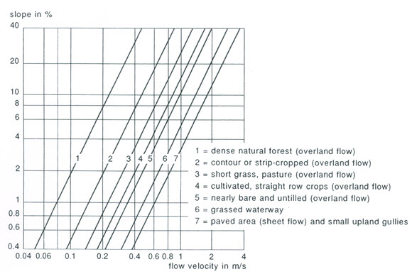
Fig. 3.1. Relation between slope and flow velocity. (Source: SCS, 1971)
From the point of view of transport duration for low flow velocities, it is recommended to limit the field length in the flow direction to 200 m or less. The amount of water that drains from graded fields as described for the first and second situations can be calculated by the Curve Number method.
In the third situation, which contains basins for irrigation or for water conservation, the surface is leveled by earthmoving machinery (large basins) or with simple farm implements (small basins in traditional rice farming). Leveled fields are surrounded by field bunds. Any excess water from basins is usually drained through an overflow in the field bunds that spills the water directly into a field drain. In large rice fields (up to 6 ha in Surinam), under fully mechanized farming; the overflow is replaced by a gated culvert with a diameter of up to 0.6 m. In this situation, bunds are made by earthmoving machinery and are often used as farm roads.
In general, land grading is done with a combination of conventional earthmoving equipment and specially designed machinery (Haynes, 1966). The benefits derived from land grading will often depend on good maintenance in subsequent years. The land should be smoothed each time a field has been plowed. This will ensure settlement in fill areas and will erase dead furrows and back furrows. A small leveler or plane powered by a tractor can be used for this purpose.
3.4 Land Grading Calculation
A land-grading design comprises estimation of the best field slope from a topographic and soil survey taking into account the plans for irrigation and drainage systems and field roads. The area should be cleared of vegetation and the surface prepared for the operation. Land grading/leveling is an intensive practice and much expenditure can be saved if the area is carefully divided into sub-areas having almost the same slope and soil conditions.
Field data are normally obtained from a topographic survey (standard grid survey using a surveying instrument) with ground elevations taken to the nearest 0.01 m on a 30-m square grid for horizontal control. Elevations are taken at other critical such as highs and lows between grid stakes, and the water surface in the supply ditch or in the drainage outlet. These days, laser surveying (using laser-controlled equipment consisting of a laser transmitter and a tractor-operated scraper fitted with a laser receiver) is also used for obtaining elevations of the land surface. Laser survey is more accurate and less time consuming than the conventional grid survey (Schwab et al., 2005). After obtaining a desired balance between cuts and fills, the volume of earthwork is computed.
Of the several methods available for calculating cuts and fills, two widely used methods are plane method and profile method, which are discussed in this lesson. Computer software is commercially available or one can develop his own computer program to solve land grading/leveling problems.
3.4.1 Plane Method
The plane method is so called because the resulting land surface has a uniform downfield slope and a uniform cross slope. The plane method, also known as the ‘method of least squares’, makes it possible to calculate a balanced cut-and-fill for regular as well as for irregular fields. The step-by-step procedure is as follows:
Step 1: Complete the design and construction survey.
Step 2: Determine the initial elevation at each grid point (Ei).
Step 3: Subdivide the area into sub-areas, each of which can be leveled to a plane surface.
Step 4: Locate the centroid of the sub-area (xc, yc).
To give equal cut and fill, the plane must pass through the centroid. The centroid of a rectangular field is located at the intersection of its diagonal. The centroid of a triangular field is located at the intersection of lines drawn from its corners to the midpoints of the opposite sides.
The centroid coordinates of an irregular field are given as follows:
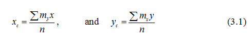
Where, xc, yc = coordinates of the centroid of the sub-area (m), x, y = coordinates of the grid lines (m), mx = number of grid points on grid line in x direction, my = number of grid points on grid line in y direction, and n = total number of grid points (åmx = åmy = n).
Step 5: Calculate the average elevation of the sub-area at the centroid (Ec) as:
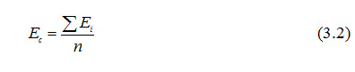
Where, Ec = average elevation of the sub-area at the centroid (m), Ei = initial elevation of grid point (m), and n = total number of grid points.
Step 6: With the desired sx and sy slopes, in x and y direction respectively, and the average elevation Ec (Ec usually has to be lowered 1 or 2 cm to satisfy the desired cut/fill ratio), the new elevation of the grid points can now be calculated. The new plane passes through the centroid, and hence the elevation of the origin (Eo) will be:
![]()
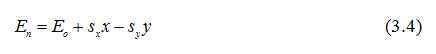
The new elevations of the grid points will be:
After being graded, soil will settle in the filled areas and expand, after being plowed, in the cut areas. To take this into account, calculations for cuts and fills must be adjusted prior to grading (SCS, 1983). Table 3.2 summarizes some recommended cut/fill ratios for different soil types.
Table 3.2. Cut/fill ratios for various soils (Source: Coote and Zwerman, 1970)
|
Sl. No. |
Soil Type |
Cut/Fill ratio |
|
1 |
Coarse-textured Soils (sandy) |
1.1 : 1 to 1.2 : 1 or 110 to 120% |
|
2 |
Medium-textured Soils (clay-loam) |
1.2 : 1 to 1.3 : 1 or 120 to 130% |
|
3 |
Fine-textured Soils (clayey) |
1.3 : 1 to 1.4 : 1 or 130 to 140% |
|
4 |
Organic Soils |
1.7 : 1 to 2.0 : 1 or 170 to 200% |
Using the plane method, we avoid unnecessary earthmoving and find the best fitting plane for any area. If it is obvious from the topography that the best fitting slope is outside the limits (e.g., imposed by erosion hazards), we omit the next calculation and apply the acceptable limit. For non-rectangular fields, the best-fitting slopes sx and sy can be calculated as:
Where, åx2 = sum of the square abscissa of each grid point (m2), åy2 = sum of the square ordinate of each grid point (m2), åxy = sum of the products of the coordinates of each grid point (m2), åxEi = sum of the products of abscissa and elevation of each grid point (m2), åyEi = sum of the products of ordinate and elevation of each grid point (m2), and n = total number of grid points.
Note that for rectangular areas, the term åxy - nxcyc becomes zero.
Step 7: Finally, calculate the volume of earthwork. Knowing the initial and new elevation, we can determine the cut and fill in each grid square and can calculate the total volume of soil to be moved as:

Where, V = volume of soil to be moved (m3), åC = sum of all cuts (m) (C = Ei – En > 0), and A = area of grid square (m2).
Example Problem on Plane Method (Source: Coote and Zwerman, 1970):
An irregular-shaped field has to be leveled. A topographic survey was made with the use of a 25 m grid, the grid lines being set out in the direction of the rows (direction of y-axis in Fig. 3.2). In this figure, the elevations are indicated above at the left of the grid points.
The average row length is 225 m. We are dealing with a fine-textured (clayey) soil, so the row grade can vary between 0.05 and 0.25% (Table 3.1). The required cut/fill ratio is 1.40.
Solution: The plane method is used to calculate required cuts and fills. The calculations are as follows (see also Fig. 3.2):
Using Eqn. (3.1): xc = 88.68 m equal yc = 123.11 m.

Fig. 3.2. Plane method of land grading.
(Source: Coote and Zwerman, 1970)
Using Eqn. (3.2): Ec = ∑Ei /n = 159.44/53 = 3.01 m
nxc2 = 416 792, nyc2 = 803 314, nxcyc = 578 632,
nxcEc = 14139, and nycEc = 19629.
Now, ∑x2 = 511 250, ∑y2 = 1 018 125, ∑xy = 585 000,
∑xEi = 14183, and ∑yEi = 19967.
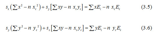
Using Eqn. (3.5): sx (511 250 – 416 792) + sy (585 000 – 578 632)
= 14183 – 14139
And using Eqn. (3.6): sy (1 018 125 – 803 314) + sx (585 000 – 578 632)
= 19967 – 19629.
\ sx = 0.00036 m/m or 0.036%, and sy = 0.00158 m/m or 0.158%.
From Eqn. (3.3), Eo = 3.01 – 0.00036 × 88.68 – 0.00156 ×123.11 = 2.78 m, and from Eqn. (3.4), En = 2.78 + 0.00036x + 0.00156y.
By definition, the plane of best fit has equal cuts and fills:
|
Row No. → |
A |
B |
C |
D |
E |
F |
å |
|
Cuts |
0.12 |
0.19 |
0.18 |
0.18 |
0.25 |
0.09 |
1.01 |
|
Fills |
0.17 |
0.19 |
0.17 |
0.13 |
0.13 |
0.22 |
1.02 |
To satisfy the required cut/fill ratio of 1.40, the plane of best fit is lowered 0.01 m. The cut/fill ratio now becomes:
|
Row No.→ |
A |
B |
C |
D |
E |
F |
å |
|
Cuts |
0.20 |
0.22 |
0.22 |
0.22 |
0.29 |
0.12 |
1.28 |
|
Fills |
0.09 |
0.16 |
0.13 |
0.10 |
0.10 |
0.18 |
0.76 |
Therefore, Cut/fill ratio = 1.28/0.76 = 1.68.
This cut/fill ratio is higher than the required one. If this is not acceptable, the calculation can be repeated with a lowering of 0.005 m. In the present case, we can assume that the accuracy of leveling is around 0.01 m, and hence we can accept the calculated cut/fill ratio of 1.68. This results in a total earthwork volume (V) as:
From Eqn. (3.7), m3, Ans.
For each grid point in Fig. 3.2, the final cut or fill is shown below on the right of the grid point.
3.4.2 Profile Method
Profile method is generally appropriate for land grading on comparatively flat lands. It is not as accurate as the plane method, but it should be adequate for surface drainage. The new grade of the field will not be uniform, but will be continuous to the field drains. With this method, ground profiles are plotted and a grade is established that will provide an approximate balance between cuts and fills and will restrict haul distances (distance between the center of the mass of excavation and the center of mass of the fill) to reasonable limits. The step-by-step procedure is as follows:
Step 1: Complete the design and construction survey.
Step 2: Plot the elevations of the grid points on each grid line in the direction of the greatest slope or the direction in which row drainage is desired.
Step 3: Draw a profile of the existing land surface along the grid line.
Step 4: Draw a new profile for each grid line by trial and error, knowing the allowable slope limits and the desired cut/fill ratio.
Step 5: Plot the cross profiles to check wheather they exceed the limits (these limits need not be the same as those chosen for the row grade).
Step 6: Calculate the volume of earthwork.
On the basis of earthmoving calculations, haul distances, and the location at which land grading/leveling operation is to take place, a drainage contractor is able to prepare a cost estimate for the land grading/leveling operation.
3.5 Design Consideration for Field Drains and Field Laterals
3.5.1 Design Consideration for Field Drains
Field drains for a surface drainage system have a different shape from field drains for a subsurface drainage system. Field drains for surface drainage have to allow farm equipment to cross them and are easy to maintain with ordinary mowers. Surface runoff reaches the field drains by flow through row furrows or by sheet flow. In the transition zone between drain and field, flow velocities should not induce erosion.
Field drains are shallow and have flat side slopes. They are often constructed with land planes as used in land forming. Simple field drains are V-shaped. The dimensions of V-shaped field drains are determined by the construction equipment, maintenance needs, and crossability for farm equipment. Side slopes should not be steeper than 6 to 1. Nevertheless, long field drains in conditions of high rainfall intensities, especially where field runoff from two sides accumulates in the drain, may require a higher transport capacity than provided by a simple V-shaped channel.
Without increasing the drain depth too much, the capacity can be enlarged by constructing a bottom width, creating a shallow trapezoidal shape. Recommended dimensions of V-shaped and trapezoidal drains are given in Fig. 3.3. All field drains should be graded towards the lateral drain with grades between 0.1 and 0.3%.
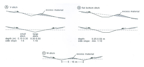
Fig. 3.3. Types of passable field collector ditches.
(Source: Smedema and Rycroft, 1983)
3.5.2 Design Consideration for Field Laterals
Field laterals collect water from field drains and transport it to the main drainage system. In contrast to the field drain, the cross-section of field laterals should be designed to meet the required discharge capacity. Besides the discharge capacity, the design should take into consideration that in some cases surface runoff from adjacent fields also collects directly in the lateral, requiring a more gentle side slope. Field laterals are usually constructed by different machinery than field drains (i.e., excavators instead of land planes). The recommended dimensions for field laterals are given in Table 3.3.
Field laterals less than 1 m deep are usually constructed with motor graders or dozers. The soil is placed near either side of the lateral. Scrapers are needed when the excavated soil is to be transported some distance away. Under wet conditions, excavators are used. Maintenance requirements should be considered during design; for example, if the field laterals are to be maintained by mowing, side slopes should not be steeper than 3 to 1. Finally, special attention should be given to the transition between field drains and laterals, because differences in depth might cause erosion at those places. For discharges below 0.03 m3/s, pipes are a suitable means of protecting those places. However, for higher discharges, open drop structures are recommended.
Table 3.3. Recommended dimensions for field laterals (Source: ASAE, 1980)
|
Sl. No. |
Type of Drain |
Depth (m) |
Recommended Side Slope (H : V) |
Maximum Side Slope (H : V) |
|
1 |
V-shaped |
0.3 to 0.6 |
6 : 1 |
3 : 1 |
|
2 |
V-shaped |
>0.6 |
4 : 1 |
3 : 1 |
|
3 |
Trapezoidal |
0.3 to 1.0 |
4 : 1 |
2 : 1 |
|
4 |
Trapezoidal |
>1.0 |
1.5 : 1 |
1 : 1 |
3.5.3 Layout and Design of Field Drains and Laterals
(1) Random Field Drain System
Random field drains are best suited to the drainage of scattered depressions or potholes where the depth of cut is not more than 1 m. In cross section, they are a flat ‘V’ or parabolic in shape (Schwab et al., 2005). The layout of a typical random field drain system is shown in Fig. 3.4. The design of field drains is similar to the design of grass waterways. Where farming operations cross the channel, the side slope should be flat, i.e., 8:1 or greater for depths of 0.3 m or less and 10:1 or greater for depths over 0.6 m. Minimum side slope of 4:1 is desired if the field is farmed parallel to the ditch.
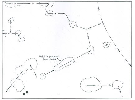
Fig. 3.4. A random field drain system. (Source: Schwab et al., 2005)
The depth is determined primarily by the topography of the area, outlet conditions, and capacity of the channel. The grade in the channel should be such that the velocity does not cause erosion or sedimentation. Minimum velocities vary with the depth of flow; however, these range from about 0.3 to 0.6 m/s for depths of flow less than 1 m. The maximum grade for sandy soil is about 0.2% and for clay soils, 0.5%. The minimum grade is 0.05%. The roughness coefficient in the Manning’s equation may be taken as 0.04, if more reliable coefficients are not available. The capacity of the drain is usually not considered for areas less than 2 ha provided the minimum design specifications are met. However, where the area is larger than 2 ha, the capacity should be based on a 10-year return period storm, making allowances for minimum infiltration and interception losses. Since most field crops are able to withstand inundation for only a short period without damage, it is desirable to remove surface water within 12 to 24 hours.
Generally, the channel should follow a route that provides minimum cut and least interface with farming operations. The outlet for such a system may be a natural stream, constructed drainage ditch, or protected slope if no suitable ditch is available. Where the outlet is a broad, flat slope, the water is permitted to spread out on the land below. This type of outlet is practical only if the drainage area is small.
(2) Bedding Field Drain System
Bedding is a method of surface drainage consisting of narrow-width plow lands in which the dead furrows run parallel to the prevailing land slope (Fig. 3.5). The area between two adjacent dead furrows is known as a bed. Bedding is most practicable on flat slopes less than 1.5%, where the soils are slowly permeable and pipe drainage is not economical. Studies have shown that the leveled land provides slightly better yield than the bedded land (Schwab et al., 2005).
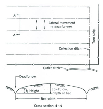
Fig. 3.5. Bedding field drain system. (Source: Schwab et al., 2005)
The design and layout of a bedding system involves the proper spacing of dead furrows, depth of bed, and grade in the channel. The depth and width of the bed depend on land slope, drainage characteristics of the soil, and cropping system. Bed widths recommended for the Corn Belt region of the United States vary from 7 to 11 m for very slow internal drainage from 13 to 16 m for slow internal drainage, and from 18 to 28 m for good internal drainage. The length of the beds may vary from 90 to 300 m. In the bedded area, the direction of farming operation may be parallel or normal to the dead furrows. Tillage practices parallel to the beds have a tendency to retard water movement to the dead furrows. Plowing is always parallel to the dead furrows.
(3) Parallel Field Drain System
Parallel field drains are similar to bedding except that the channels are spaced farther apart and may have a greater capacity than the dead furrows. This system is well adapted to flat, poorly drained soils with numerous small depressions that must be filled by land grading (Schwab et al., 2005).
The design and layout are similar to those for bedding except that drains need not be equally spaced and the water may move in only one direction. The layout of such a field system is shown in Fig. 3.6. As in bedding, the turn strip is provided where ditches border a fence line. The size of the ditch may be varied, depending on grade, soil, and drainage area. The depth of the ditch should be a minimum of 0.2 m and have a minimum cross-sectional area of 0.5 m2. For trapezoidal cross sections, the bottom width should be 2.4 m (ASAE, 1986). The side slopes should be 8:1 or flatter to facilitate crossing with farm machinery. As in bedding, plowing operations must be parallel to the channels, but planting, cultivating, and harvesting are normally perpendicular to them. The rows should have a continuous slope to ditches. The maximum length for rows having a continuous slope in one direction is 180 m, allowing a maximum spacing of 360 m where the rows drain in both directions. In very flat land with little or no slope, some of the excavated soil may be used to provide the necessary grade; however, the length and grade of the rows should be limited so as to prevent damage by erosion. On highly erosive soils that are slowly permeable, the slope length should be reduced to 90 m or less.

Fig. 3.6. Parallel field drain system. (Source: Schwab et al., 2005)
As mentioned earlier, the cross section for field drains may be V-shaped, trapezoidal, or parabolic. The W-drain shown in Fig. 3.7 is essentially two parallel single ditches with a narrow spacing. All of the spoil is placed between the channels, making the cross section similar to that of a road. The advantages of the W-drain are that it: (i) allows better row drainage because spoil does not have to be spread, (ii) may be used as a turn row, (iii) may serve as a field road, (iv) can be constructed and maintained with ordinary farm equipment, and (v) may be seeded to grass or row crops. On the other hand, the disadvantages of the W-drain are that: (i) the spoil is not available for filling depressions, (ii) a greater quantity of soil must be moved, and (ii) a larger area is occupied by drains. The minimum width for W-drains varies from about 5 to 30 m depending on the size. The W-drain is best adapted to relatively flat land where the rows drain from both directions.
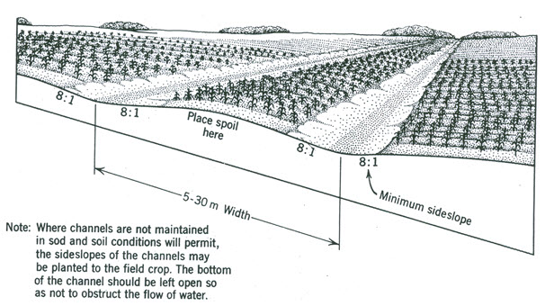
Fig. 3.7. W-drain or double field drain for surface drainage.(Source: Schwab et al., 2005)
(4) Parallel Lateral Ditch System
The parallel lateral ditch system is similar to the field drain system except that the ditches are deeper. These drains shown in Fig. 3.8 cannot be crossed with farm machinery. For clarity, the minimum size for open ditches is 0.3 m deep and side slopes are steeper than 6:1. The purpose of lateral open ditches is to control the water table and to provide surface drainage. These ditches are applicable for draining peat and muck soils to obtain initial subsidence prior to subsurface drainage. For the same depth to water table, ditches provide the same degree of surface drainage as pipe drains.
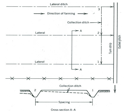
Fig. 3.8. Parallel lateral ditch system for water table control and surface drainage.
(Source: Beauchamp, 1952)
The design specifications for lateral ditches are given in Table 3.4. Since lateral ditches are considerably deeper than collection ditches, overfall protection must be provided at outlets 1 and 2 as indicated in Fig. 3.8. This protection may be obtained with a suitable permanent structure, by providing a gradual slope near the outlets, or by establishing a grassed channel. Since these ditches are too deep to cross with farm machinery, farming operations must be parallel to the ditches. A collection ditch, row drain, or quarter drain should be provided for row drainage. As in other methods of drainage on flat land, the surface must be graded and smoothed and large depressions filled or drained by random field ditches.
Table 3.4. Ditch specifications for water table control (Source: Schwab et al., 2005)
|
Sl. No. |
Parameter |
Sandy Soil |
Other Mineral Soils |
Organic Soils, Peat and Muck |
|
1 |
Maximum Spacing |
200 m |
100 m |
60 m |
|
2 |
Minimum Side Slope |
1:1 |
:1 |
Vertical to 1:1a |
|
3 |
Minimum Bottom Width |
1.2 m |
0.3 m |
0.3 m |
|
4 |
Minimum Depth |
1.2 m |
0.8 m |
0.9 m |
Note: a Vertical for raw peat to 1:1 for decomposed peat and muck.
For water table control during dry seasons, dams with removable crest boards are placed at various points in the open ditches to maintain the water surface at the required level. During wet seasons, the crest boards are removed and the system provides surface drainage (Schwab et al., 2005). In highly permeable soils such as sands, peat, and muck, crop yields may be increased by controlled drainage. Deep permeable soils underlain with an impervious material provide the best conditions for successful water table control. The water level may be regulated by gravity, pumping, or a combination of gravity drainage and pumping. The depth at which the water table is to be maintained depends mainly on the crop to be grown, soil type, topography, seasonal conditions, and climatic conditions. Note that in organic soils, a high water table is desirable to provide water for plant growth, to control land subsidence, and to reduce fire and wind erosion hazards. In these soils, the water table should be maintained from 0.5 to 1.2 m below the soil surface depending on the crop type (Schwab et al., 2005).
(5) Cross-Slope Ditch System
The drainage of sloping land may be feasible with cross-slope ditches. Such channels usually function both for surface drainage and for erosion control. Where designed specifically for the control of erosion, these drains are called terraces. Diversion ditches are sometimes used to divert runoff from low-lying areas, thereby reducing the drainage problem.
The cross-slope ditch system is adapted primarily to soils with poor internal drainage where subsurface drainage is not practicable and for land with slopes of 4% or less having numerous shallow depressions (Schwab et al., 2005). This land is generally too steep for bedding or field drains because farming up and down the slope results in excessive erosion.
3.6 Maintenance of Surface Drainage System
Field surface drains can usually be maintained by normal tillage operations. Such maintenance is particularly important on flat land because a very small obstruction in the channel may cause flooding of a sizable area (Schwab et al., 2005). Tillage implements should be lifted when crossing ditches to avoid blocking the channel. If this procedure is not followed, the channel should be kept open by dragging or shaping a smooth channel in the bottom of the drain. When the soil is wet, equipment should not cross dead furrows, field drains, or grass waterways. Moreover, livestock can also damage such channels during rainy seasons, and hence pasturing at other times is desirable. Plowing parallel to shallow surface drains, leaving the dead furrow in the channel is generally adequate for maintenance. Minor depressions between drains should be filled by land grading.
References
ASAE (1980). Design and Construction of Surface Drainage Systems on Farms in Humid Areas. ASAE Engineering Practice (ASAE EP 302-2), Agricultural Engineers Handbook 1980, American Society of Agricultural Engineers (ASAE), St. Joseph, MI, pp. 453-460.
ASAE (1986). Design and Construction of Surface Drainage Systems on Farms in Humid Areas. ASAE Engineering Practice (ASAE EP 302-3), American Society of Agricultural Engineers (ASAE), St. Joseph, MI.
Beauchamp, K.H. (1952). Surface drainage of light soils in the Midwest. Agricultural Engineering, 33(4): 208-212.
Coote, D.R. and Zwerman, P.J. (1970). Surface Drainage of Flat Lands in the Eastern U.S. Cornell. Univ. Est. Bulletin, 1224, 48 pp.
FAO (1985). Irrigation Water Management: Introduction to Irrigation. Chapter 6, Training Manual, Food and Agriculture Organization (FAO), Rome, http://www.fao.org/docrep/R4082E/ r4082e07.htm (accessed on April 29, 2013).
Haynes, H.D. (1966). Machinery and Methods for Constructing and Maintaining Surface Drainage on Farm Lands in Humid Areas. Transactions of ASAE, 9(2): 185-189,193.
ICID (1982). ICID Standard 109, Construction of Surface Drains. ICID Committee on Irrigation and Drainage Construction Techniques, ICID Bulletin 31, 1, pp. 47-57.
Schwab, G.O., Fangmeier, D.D., Elliot, W.J. and Frevert, R.K. (2005). Surface Drainage and Land Forming. Fourth Edition, John Wiley and Sons (Asia) Pte. Ltd., Singapore, pp. 245-264.
SCS (1971). Drainage of Agricultural Land. National Engineering Handbook, Section 16, Soil Conservation Service (SCS), U.S. Department of Agriculture, Washington, DC.
SCS (1983). Land Leveling. Chapter 12, National Engineering Handbook, Section 15, Soil Conservation Service (SCS), U.S. Department of Agriculture, Washington, DC.
Smedema, L.K. and Rycroft, D.W. (1983). Land Drainage. Batsford Academic and Education Ltd., London.
Suggested Readings
Murty, V.V.N. and Jha, M.K. (2011). Land and Water Management Engineering. Sixth Edition, Kalyani Publishers, Ludhiana, India.
Ritzema (Editor-in-Chief) (1994). Drainage Principles and Applications. International Institute for Land Reclamation and Improvement (ILRI), ILRI Publication 16, Wageningen, The Netherlands.
Schwab, G.O., Fangmeier, D.D., Elliot, W.J. and Frevert, R.K. (2005). Soil and Water Conservation Engineering. Fourth Edition, John Wiley and Sons (Asia) Pte. Ltd., Singapore.
Last modified: Monday, 16 September 2013, 5:04 AM