Site pages
Current course
Participants
General
Module 1: Basics of Agricultural Drainage
Module 2: Surface and Subsurface Drainage Systems
Module 3: Subsurface Flow to Drains and Drainage E...
Module 4: Construction of Pipe Drainage Systems
Module 5: Drainage for Salt Control
Module 6: Economics of Drainage
Keywords
Lesson 4 Design of Subsurface Drainage Systems
4.1 Purpose and Benefits of Subsurface Drainage
Subsurface drainage is the removal of excess water from the root zone. It is accomplished by deep open drains or buried pipe drains (FAO, 1985). Subsurface drainage is an important conservation practice. Poorly drained lands are usually topographically situated so that when drained, they may be farmed with little or no erosion hazard. Many soils having poor natural drainage are, when properly drained, rated among the most productive soils in the world.
Specific benefits of subsurface drainage are: (i) aeration of the soil for maximum development of plant roots and desirable soil microorganisms; (ii) increased length of growing season because of earlier possible planting dates; (iii) decreased possibility of adversely affecting soil tilth through tillage at excessive soil water levels; (iv) improvement of soil water conditions in relation to the operation of tillage, planting and harvesting machines; (v) removal of toxic substances, such as salts, that in some soils retard plant growth; and (vi) greater storage capacity for water, resulting in less runoff and a lower initial water table following rains. Through these benefits drainage enhances farm productivity by: (a) adding productive land without extending farm boundaries, (b) increasing yield and quality of crops, (c) permitting good soil management, (d) ensuring that crops may be planted and harvested at optimum dates, and (e) eliminating inefficient machine operation caused by small wet areas in fields. In arid regions irrigation and drainage are complementary practices. In some areas leaching of soluble salts through a drainage system is essential before the land can be developed. Drainage is often a necessity as a result of excess water that accumulates from low efficiencies in the conveyance and application of water for irrigation. Although these losses can be reduced, they cannot be entirely eliminated. The benefits of drainage can be realized only when the soil is potentially productive if drained. Government regulations may require leaving soil undrained as a range land or as a recreation and wildlife area.
4.2 Types of Subsurface Drainage Systems
If one has decided to install a subsurface drainage system, one has to make a subsequent choice between well drainage, open drains, pipe drains, and mole drains. Well drainage and mole drainage are applied only in very specific conditions (refer to Lessons 8 and 12). Also, mole drainage is mainly aimed at a rapid removal of excess surface water, not controlling water table. Therefore, the usual choice is between open drains and pipe drains (Cavelaars et al., 1994). This choice has to be made at two levels: (a) for field drains, and (b) for collectors. If the field drains are to be pipe drains, there are still two options for the type of collectors: (i) they can be open drains so that we have a ‘singular pipe-drain system’, or (ii) they can be pipe drains so that we have a ‘composite pipe-drain system’.
Open drains have the advantage that they can receive overland flow directly, but the disadvantages often outweigh the advantages. The main disadvantages are: loss of land, interference with the irrigation system, splitting-up of the land into small parcels that hamper mechanized farming operations, and the burden of maintenance. Nevertheless, there are cases where open drains are used exclusively, e.g., peat soils and very saline land under a monoculture of rice.
Moreover, a combined system of surface and subsurface drainage may be more appropriate in certain field situations. Salient examples are as follows:
A soil profile with a layer of low permeability below the root zone, but good permeability at drain depth: This is a soil profile that can be found in alluvial soils throughout the world. After a heavy rain, a perched water table forms in the root zone, which cannot be lowered rapidly enough without some form of surface drainage. Subsurface drainage subsequently lowers the water table to a normal depth. An alternative solution could be to break up the impeding layer by subsoiling, especially if the impeding layer is less than about 0.3 m thick.
Areas with deep frost penetration and snow cover during winter: When the snow melts and the topsoil thaws, but soil at some depth is still frozen, a perched water table will form and will damage a crop of winter grain. The same measures as in the previous example are required here;
Irrigated land in arid and semi-arid regions, where the cropping pattern includes rice in rotation with ‘dry-foot’ crops (e.g., as in the Nile Delta in Egypt): Subsurface drainage is needed for salinity control of the dry-foot crops, whereas surface drainage is needed to evacuate the standing water from the rice fields (e.g., before harvest).
Areas with occasional high-intensity rainfall that causes water ponding on the land surface, even if a subsurface drainage system is present: The ponded water could be removed by the subsurface drainage, but this may either take too long time or require very narrow drain spacings. Under such circumstances, it would be more efficient to remove the ponded water by surface drainage.
4.3 Design of Pipe Drainage Systems
Pipe drainage is probably the most widely used subsurface drainage method worldwide. Pipe drainage projects can vary widely in scope and size. A project may be a single farm, or it may cover several hectares of land. In this lesson, we will assume a comprehensive large-scale pipe drainage project, because it offers a suitable field setting to discuss all the relevant aspects of a pipe drainage system.
4.3.1 Layout of Pipe Drainage Systems
In this section, we shall discuss the most important considerations that lead to a designed spatial arrangement of a subsurface drainage system in an area (i.e., showing all the items on a map). These considerations involve the choice between a singular system and a composite system, the location and alignment of drains, subsurface drainage in rice fields as a special case, and the use of multiple small pumping stations (Cavelaars et al., 1994). A brief description on singular and composite drainage systems is provided below.
(1) Overview of Singular and Composite Drainage Systems
In a singular pipe drainage system, each field pipe drain discharges into an open collector drain. In a composite pipe drainage system, the field pipe drains discharge into a pipe collector, which in turn discharges into an open main drain. The collector system itself may be composite with sub-collectors and a main collector.
The layout of a pipe drainage system is called a ‘random system’ when only scattered wet spots of an area need to be drained, often as a composite system (Fig. 4.1A). A regular pattern can be installed if the pipe drainage network uniformly covers the project area. Such a regular pattern can either be a ‘parallel grid system’ wherein the field drains join the collector at right angles (Fig. 4.1B), or a ‘herringbone system’ wherein they join at sharp angles (Fig. 4.1C). Note that both the regular patterns may occur as a singular system or a composite system.
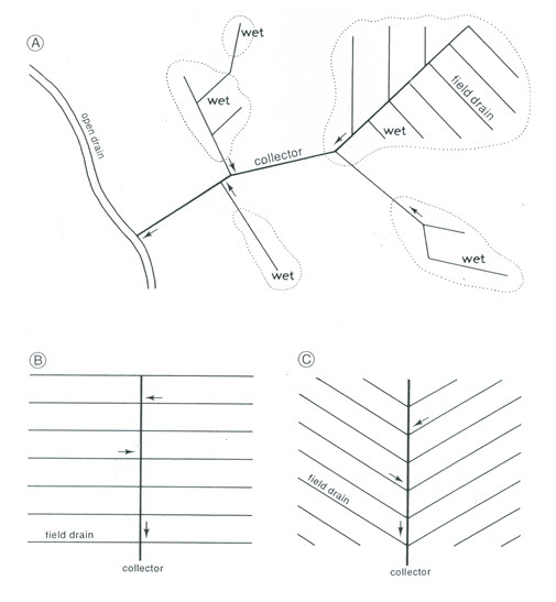
Fig. 4.1. Different layout patterns for a composite pipe drainage system: (A) Random system;
(B) Parallel grid system; and (C) Herringbone system.(Source: Cavelaars et al., 1994)
(2) Selection Criteria for Singular and Composite Drainage Systems
The choice between a singular and a composite system must be based on a number of factors such as the desirability of open drains, head loss, and costs. A singular system implies a comparatively dense network of open collector drains (maximum spacing in the order of 500 m). These open drains have disadvantages as discussed in Section 4.2, but they may be desirable for other reasons, for example, to provide open water storage and additional surface drainage in high-rainfall areas. A composite pipe system, supplemented by an independent system of shallow surface drains could be another option.
In many flat areas in temperate regions, a natural network of open drains exists before the introduction of a subsurface drainage system. Turning such drains into open collectors may then be convenient, thereby deciding against a composite system (Cavelaars et al., 1994). There are certain advantages and disadvantages of a singular drainage system. Singular drainage system has many pipe outlets, which are vulnerable to damage. Conversely, the maintenance of a singular system is easier and can be done by using standard flushing equipment. Another major consideration is that the construction costs are normally higher for pipe collectors, but the long-term maintenance costs are much lower than for open collectors. Further, in low-lying flat areas, the costs of the main drainage system and pumping station also have to be considered.
However, in irrigated areas with a rather complex infrastructure of roads, irrigation canals, and small farm plots (e.g., as in Egypt), composite systems are generally preferred (Cavelaars et al., 1994). Open collector drains can interfere too much. Singular systems with open collector drains are feasible in the areas where the infrastructure has been fully remodelled under a land consolidation scheme (e.g., as in Iraq), or in newly reclaimed areas. Such considerations have led to a general practice of selecting singular systems in the flat areas of temperate climates and, occasionally, in the irrigated land of arid regions, whereas composite systems are selected in sloping land and, commonly, in the irrigated land of arid regions (Cavelaars et al., 1994).
4.3.2 Location and Alignment of Drains
The problem is how to draw a drainage system on the map. In many cases, there are several options open to drainage design engineers. However, two main factors viz., topography and existing infrastructure should provide guidance. Optimum use should be made of the existing topography in order to achieve a depth-to-water table as uniformly as possible throughout the area. In the case of uneven topography, the drains will, as much as possible, be situated in the depressions. Fig. 4.2 shows an example of a flat area in a temperate climate, where, fields usually have a regular pattern of shallow depressions, which are the remains of old surface drainage systems. Fig. 4.2A shows how to install field drains in these depressions, even if the spacing does not exactly match with the calculated spacing. Fig. 4.2B shows how it should not be done. A second example (Fig. 4.3) shows where the collector is to be installed in a ‘thalweg’, which is the line joining the lowest points along a valley.
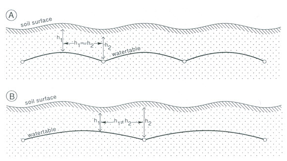
Fig. 4.2. Location of field drains in relation to field topography: (A) Well-adapted; (B) Poorly adapted.
(Source: Cavelaars et al., 1994)
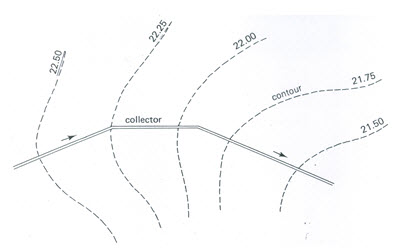
Fig. 4.3. Location of the collector adapted to the contour lines. (Source: Cavelaars et al., 1994)
In an area with a uniform land slope (i.e., with parallel equidistant contours), the collector is preferably installed in the direction of the main slope, while the field drains run approximately parallel to the contours (Fig. 4.4A). To take advantage of the slope for the field drains also, a herringbone system can be applied. Other alternatives are collectors parallel to the contours, and the field drains down the slope (Fig. 4.4B), and collectors and field drains both at an angle to the contours (Fig. 4.4C). A major drawback of the latter two alternatives is that the field drains are only on one side of the collector. The inherent greater total collector length and the consequent higher costs make these solutions suitable only under special conditions.
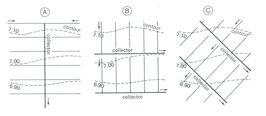
Fig. 4.4. Pipe drainage layout adapted to a uniform slope of the land surface:
(A) Collector in the direction of the slope;(B) Field drains in the direction of the slope;
(C) Collector and field drains at an angle to the slope. (Source: Cavelaars et al., 1994)
When an infrastructure exists, it has almost certainly been designed without consideration being given to a pipe drainage system. Only when the area has originally been developed under a large-scale scheme, there is a chance that pipe drainage can be introduced in a rational way. Where the infrastructure is very old and has developed gradually in the course of history, the pattern is generally far from regular and allowances have to be made. To design a pipe drainage layout in such an area implies continuous compromises (Cavelaars et al., 1994).
Firstly, it has to be verified whether boundaries between farm holdings have to be respected as limits for pipe drainage units. It may vary from country to country and even from project to project. As an example, in The Netherlands and other Western European countries, pipe drains are as a rule installed on an individual farm basis. However, in large-scale drainage schemes in Pakistan (Khairpur) and Egypt (the Nile Delta), one drainage unit (i.e. the area served by a collector) serves the area of several farm holdings, so that collectors, and even field drains, commonly cross holding limits. Secondly, an important guideline is to keep crossings of pipe drains with channels and roads to a minimum. Especially if composite systems are installed, however, some crossings are unavoidable. The general rule is then to install the field drains parallel to the tertiary irrigation/drainage channels, and the collectors at right angles.
In new reclamation or land-consolidation schemes, the entire network of roads, irrigation canals, open drains, and pipe drains can be designed simultaneously, which logically offers the best possibility of an optimum layout. Fig. 4.5 shows two possible options for such a case: a composite system (Fig. 4.5A) or a singular system (Fig. 4.5B).
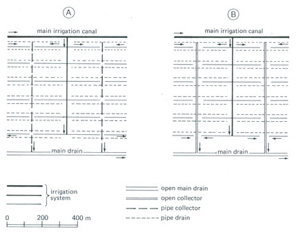
Fig. 4.5. Irrigation and drainage layout in a new land consolidation area: (A) Composite drainage system with pipe collectors;
(B) Singular drainage system with open collectors. (Source: Cavelaars et al., 1994)
4.3.3 Structures of Pipe Drainage Systems
The pipe drainage system consists not only of pipes but also of additional provisions for connection, protection, inspection, maintenance, etc. In this section, we will discuss the most common structures of a pipe drainage system such as ‘pipe outlets’, ‘pipe drain connections’, ‘closing devices’, ‘drain bridges’, and ‘surface water inlets’. These structures constitute integral parts of a pipe drainage system, and hence they are very important for the complete design of a pipe drainage system.
(1) Pipe Outlets
A good drain outlet is of great importance due to the fact that a high percentage of failures of drainage systems are due to faulty outlets. The requirements of a good drain outlet are (Schwab et al., 2005): (i) to provide a free outlet with minimum maintenance, (ii) to discharge outflow without serious erosion or damage to the pipe (iii) to keep out rodents and other small animals, (iv) to protect the end of the drain against damage from the tramping of livestock as well as excessive freezing and thawing, and (v) to prevent the entrance of flood water where the outlet is submerged for several hours.
The two main types of outlets for pipe drainage systems are (Schwab et al., 2005): gravity outlet and pump outlet. Gravity outlets are the most common, which include other pipe drains, artificial waterways, natural channels, and wells. Pump outlets may be considered where the water level at the outlet is higher than the bottom of the pipe outlet for any extended period. Outlet ditches should have sufficient capacity to carry surface runoff and drain flow. Where the drainage system is connected to other pipe drains, the outlet should have sufficient capacity to carry the additional discharge. Some type of grille or flap gate over the end is desirable to prevent entry of rodents. If there is danger of flood water backing up into the drain, an automatic flood or tide gate may be installed in place of the flap gate.
Moreover, the end of the outlet pipe should be 0.3 m or more above the normal water level in the ditch. To prevent damage caused by high velocities in the ditch or failure from snow loads, the exposed end of the pipe should not extend beyond the bank more than one third its total length. The minimum total length should be 5 m, and the diameter should be the same or larger than the drain pipe size. In connecting the metal pipe to the drain, a concrete collar may be installed. Where available, drop inlets and other permanent structures are suitable for stabilizing the outlet. Other types of outlets are vertical drainage outlets, which are essentially wells extending into a porous soil layer or open rock formation in the lower horizons.
Generally, vertical outlets are not recommended because of greater uncertainty in determining their capacity and the risk of groundwater pollution. In horizontal outlets at the place where a subsurface pipe discharges into an open drain, the side slope of the drain is subject to erosion by the normal drain outflow, while additional water may also lead to local erosion of the backfilled trench. This additional water may come from surface irrigation or from water that leaves the pipe through joints or perforations just before the outlet. The same spot is further vulnerable because small animals (e.g., frogs, rats, etc.) may enter the drain and block it.
For collector outlets (few in number), it is common to build a concrete or masonry structure. In order to avoid problems with the mechanical maintenance of open drains, the outlet structure can be built in a recessed area (Fig. 4.6).
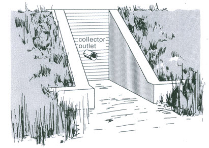
Fig. 4.6. Collector outlet in a recessed area. (Source: SCS, 1971)
Field drain outlets in a singular drainage system are many, and hence they should generally be inexpensive. An additional requirement is that the outlet should not obstruct the mechanical maintenance of the open drains. Two possible solutions are as follows:
Provision of a long outlet pipe: The outlet pipe should be long enough so that the discharge does not fall on the side slope, rather it should fall on the water surface of the open drain. The additional length to the pipe outlet should be provided such that it can be temporarily removed to allow mechanical ditch cleaning.
Provision of a drain pipe that does not protrude from the side slope: In this case, the side slope is protected by a chute made of flexible material such as plastic reinforced with glass fiber.
Note that cheap outlet structures are easily damaged. Therefore, regular inspection and repair of outlet structures is required. Additional precautions for collector and field drain outlets are to provide a removable grating in order to prevent the entry of small animals into the pipe (especially for relatively large diameter pipes) and to prevent additional water flow at the end of the trench. For this purpose, the last section of the pipe should have neither perforations nor open joints; no envelope material (especially no gravel) should be applied near the outlet; and the last few metres of the trench backfill should be well compacted over the entire depth of the trench.
(1) Pipe Connections
There are two main types of connections: blind junctions and manholes (or inspection chambers). Blind connections are direct connections between field drains and collectors by means of cross-joints or T-joints. It is recommended to have the field drain inflow at a somewhat higher level than the collector (a ‘drop-in’ of about 0.10 m). Blind connections can be provided with special arrangements so that the field drains can be cleaned by flushing without having to excavate and dismantle the connection (Fig. 4.7).
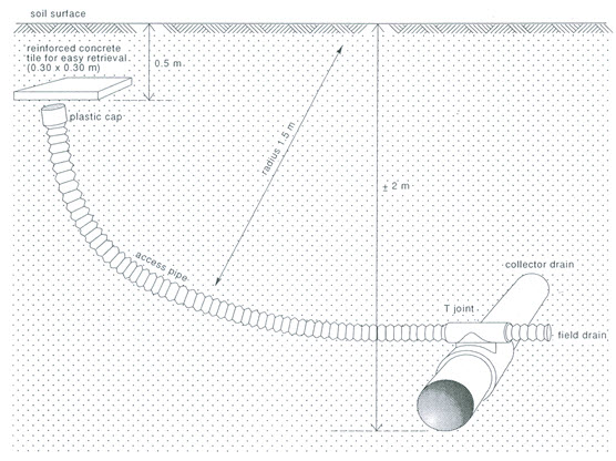
Fig. 4.7. Connection of field drain to collector drain with access pipe to allow entry of jetting or rodding
equipment.(Source: Cavelaars et al., 1994)
A manhole allows inspection and maintenance of the field drains and the collector. The lid may be either above or below the land surface (Fig. 4.8), depending on the need for frequent inspection. A disadvantage of having the lid at the surface is that farmers tend to use the structure as an outlet for excess irrigation water, which will inevitably lead to extra sedimentation in the drain. If the lid is underground, the location should be well recorded for easy retrieval. A useful help is to cast some iron in the lid so that it can easily be found later with a metal detector.
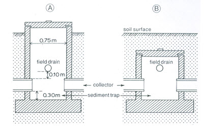
Fig. 4.8. Manhole: (A) Cover above soil surface; (B) Buried cover.
(Source: Cavelaars et al., 1994)
Recommendations for the construction of manholes include the floor to be some 0.20 to 0.30 m below the collector invert, thus allowing for a ‘silt trap’, from which sediment can be easily removed. A drop between the field drain and the collector of about 0.10 m is recommended. To allow access by a man, the inside diameter of the manhole should be at least 0.75 m, and, if the structure is deep, a ladder of iron bars should be cast in the wall. The manhole can be made of pre-cast segments, of cast-in-place concrete, or of masonry.
(1) Closing Devices and Outflow Regulators
There may be reasons to close or reduce pipe outflow temporarily (e.g., if the field is under rice). A device can be designed for installation in a sub-collector or in a field drain, either at its outflow into an open drain or at its outflow into a collector. Various types of closing devices and outflow reducers have been tested, but none seems to have progressed beyond the prototype stage. Fig. 4.9 shows an example of a regulating device for sub-collector flow, to be installed in a manhole. Even if working properly, a regulating device for each field drain means a very vulnerable system, which would require meticulous maintenance.
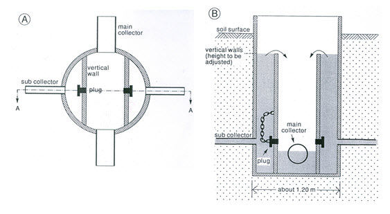
Fig. 4.9. Prototype of a closing device in a manhole: (A) Top view; (B) Section A-A.
(Source: Cavelaars et al., 1994)
(1) Drain Bridges
Where a pipe drain crosses an unstable strip of soil (e.g., a recently filled-in ditch), it may get out of line or become damaged as a result of the soil setting. As a precaution, the drain can be supported by a rigid bridge across the unstable strip. This bridge can be made of wood or of a steel pipe around the pipe drain.
(2) Surface-Water Inlets
Surface-water inlets can be built into the drain in places where surface water is likely to accumulate. Two possible types are blind inlets and open inlets. Considering the sedimentation risk involved, surface water inlets are not very common. Surface water should preferably be evacuated through a network of open drains. Blind inlets consist of a cover of stones and gravel extending from the ground surface to the drain pipe (Fig. 4.10). These inlets by nature are susceptible to clogging by soil particles at the ground surface.
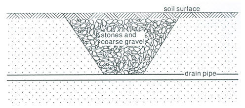
Fig. 4.10. Blind inlet for surface water into a pipe drain. (Source: SCS, 1971)
Open inlets (Fig. 4.11) are positioned preferably at the upstream end of the drain pipe in order to reduce the chance of the pipe being blocked by sedimentation. These structures should always be provided with a silt trap. At the soil surface, they should be protected by some form of grating. The silt trap must be regularly checked and cleaned.
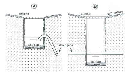
Fig. 4.11. Open inlets for surface water into a pipe drain: (A) Built beside the drain line;
(B) Built in the drain line. (Source: Cavelaars et al., 1994)
4.3.4 Depth and Spacing of Field Drains
Ideally, the depth and spacing of field drains are determined with the help of drainage equations discussed in Lessons 6 and 7. Drainage criteria are formulated in terms of the parameters that fit in these equations. The parameters, characterizing soil hydraulic properties, are obtained from field investigations. The results of this approach are an infinite number of possible combinations of depth and spacing. However, in practice, depth can seldom be selected freely, thereby restricting the spacing options (Cavelaars et al., 1994). Depth-limiting factors are: ‘drainage base’, ‘presence of unsuitable layers in the soil profile’, and the ‘available machinery’.
(1) Drainage Base
The drainage base can be defined as the water level at the outlet. It determines the hydraulic head available for drainage flow. The outlet is different for different points of a drainage area. For groundwater, the drainage base is the water level or the hydraulic head in the field drains, whether they are pipes or open drains. For the pipe drainage system, the drainage base is the water level that can be maintained in the recipient main drains. For a gravity-flow main drainage system, the drainage base consists of the water level prevailing critical periods, below the main outlet structure.
For pipe drains, we must ensure that they have a free outflow, meaning a pipe invert level at least about 0.10 m above the water level in the recipient drain. This holds for field drains discharging into a collector as well as for collectors discharging into an open main drain. Occasional submergence of short duration (e.g., 1 to 2 days or 2 to 3 times per season) is, however, usually permissible (Cavelaars et al., 1994).
As ideal conditions (i.e., flat) are rare, the drainage base may be too high in parts of the area. It is then often a matter of professional judgement to find a compromise between insufficient drainage in a limited area and high costs for over-draining the majority of the area (e.g., by including pumping). In some cases, the local effect of insufficient drainage can be offset by other measures such as adding extra nitrogen to compensate for insufficient soil aeration in the winter season in temperate regions, or, in arid areas with saline seepage, by giving an extra leaching irrigation after the fallow period (Cavelaars et al., 1994).
(2) Unsuitable Soil Layers
Certain soil textures are unsuitable for the installation of pipe drains. When a layer of such a soil texture occurs in the soil profile, the pipe drains should be installed above or below that layer (Cavelaars et al., 1994). Examples of such risky layers are quick-sand layers and slowly-permeable clay layers. Quick-sand layers are sandy layers that develop sloughing when saturated, and they pose a great risk of rapid sedimentation and of misalignment of the pipeline. Clay layers of very low permeability would lead to very narrow drain spacings, and hence high costs.
A typical example is a three-layered soil profile that can be found in alluvial soils. It consists of a root zone of good permeability, overlying a slowly-permeable clay horizon, followed by a permeable subsoil of coarse-textured soil or well- structured clay. If the permeable third layer is not too deep, the drains should preferably be installed in that layer. In this case, the pattern of groundwater flow will be: a short distance of vertical flow through the slowly-permeable second layer, and horizontal and radial flow in the permeable third layer. If the third layer consists of unstable sand, one should be aware of construction problems.
Moreover, in the case of a two-layered profile, with a permeable top soil underlain by a deep slowly-permeable substratum, the drains should be installed in the upper layer (e.g., just above the second layer). If the upper soil layer is very shallow, pipe drainage is not likely to be appropriate at all. In this case, mole drainage or surface drainage might be better alternatives.
(3) Drain Spacing
Calculated drain spacings for a project area are likely to show considerable variations due to a natural variation in soil hydraulic conductivity over a field. If the variation in soil hydraulic conductivity is significant, the area to be drained should be divided into sub-areas or ‘blocks’ of a suitable size, and for each of which a uniform and representative drain spacing is selected (Cavelaars et al., 1994). For example, a suitable size could be the area served by one collector.
After considering the depth of the drainage base and the presence of unsuitable soil layers, one normally arrives at a range of possible drain spacings. Within this range, a number of standard spacings should be selected beforehand, each standard differing from the next one by a factor of 1.25 to 1.5 (Cavelaars et al., 1994). It makes little sense to make the increments too small in view of the many inaccuracies and uncertainties in the entire process of determining drain spacings. As an example, let’s assume that the calculated drain spacings in a project area vary from 18 to 85 m (after ignoring a few extreme values). In this case, practical sets of standard drain spacings could be: 20–25–30–40–50–60–80 m, or 20–30–45–60–80 m (Cavelaars et al., 1994).
4.3.5 Pipe Diameter and Gradient
This section deals with two important factors viz., pipe slope and drainage coefficient which decide the size of a drain pipe and its gradient. The hydraulic design of a drain pipe (i.e., selection of slope and diameter) is based on the value of drainage coefficient (q). The value of drainage coefficient is not always the same as the drainage coefficient used to calculate drain spacing. The steady-state criterion for the calculation of the drain spacing, often expressed as the ratio q/h (i.e., drainage coefficient divided by the hydraulic head midway between the drains), is generally based on average monthly or seasonal values and the design discharges for the hydraulics of drainage pipes on higher, less frequent, peak discharges as may occur during a shorter period, e.g., 10 days (Cavelaars et al., 1994). Furthermore, it is inherent in the steady-state approach that the water table may be incidentally higher than the designed value. This also means that drain discharges will be higher. In very general terms, one tries to avoid the design discharge being exceeded more than ‘only a few times’ during the main drainage season.
Nevertheless, especially in areas with a very uneven topography, the permissible maximum slope may be an additional matter of concern. This slope is dictated by the maximum permissible flow velocity, for which German standards suggest 1.5 m/s for concrete pipes (Cavelaars et al., 1994). Maximum slopes are of practical significance only for collectors. If the topography necessitates steeper slopes, drop structures should be built into the pipeline, which are normally incorporated in manholes. Special caution is needed if a steep slope changes to a flatter slope; high pressures may develop at the transition point unless the flow velocity on the upstream side is properly controlled and the downstream (flatter) reach of the pipeline has a sufficient capacity.
4.4 Computer Modeling for Drainage Design
Modern computers simplify the design of a subsurface drainage system and make possible the incorporation of other variables such as climate and plant growth factors so as to predict relative crop yields. Several computer software packages have been developed, out of which most popular software package is DRAINMOD (Skaggs, 1980). DRAINMOD has the capability of handling hourly and daily weather data, soil properties, crop characteristics, soil water distribution, and other related factors. It has been widely adopted in the eastern United States and a user’s manual and computer program are available. This software is accessible in state SCS offices and has been accepted by many extension and research engineers in the humid states (Schwab et al., 2005).
DRAINMOD generates the number of working days for tillage operations, a quantitative evaluation of excess wetness conditions, the number of dry days with deficient soil water, and the yield effects of these stresses. It can also evaluate drainage system design for wastewater treatment. DRAINMOD can simulate the performance of a given drainage system for as many years of climatic record as desired. It can predict relative crop yields for the period of record from which economic probability analysis can be made. Surface drainage inputs can be evaluated, together with the effect of subirrigation through the existing drainage system. One of DRAINMOD’s greatest merits is its ability to predict crop response to the changes in drainage or subirrigation system design. One or more design parameters can be changed without affecting others.
Moreover, an indigenous and user-friendly software package named DrainSolver has been developed by Prof. Madan Kumar Jha of IIT Kharagpur (developer of this course) which facilitates computer-aided design of surface and subsurface drainage systems, simulation of subsurface flow to drains, computation of design drain discharge and leaching requirements, economic analysis of drainage systems, and the analysis of special drainage problems.
References
Cavelaars, J.C., Vlotman, W.F. and Spoor, G. (1994). Subsurface Drainage Systems. In: H.P.Ritzema (Editor-in-Chief), Drainage Principles and Applications, International Institute for Land Reclamation and Improvement (ILRI), ILRI Publication 16, Wageningen, The Netherlands, pp. 827-929.
FAO (1985). Irrigation Water Management: Introduction to Irrigation. Chapter 6, Training Manual, Food and Agriculture Organization (FAO), Rome, http://www.fao.org/docrep/R4082E/ r4082e07.htm (accessed on April 29, 2013).
Schwab, G.O., Fangmeier, D.D., Elliot, W.J. and Frevert, R.K. (2005). Soil and Water Conservation Engineering. Fourth Edition, John Wiley and Sons (Asia) Pte. Ltd., Singapore.
SCS (1971). Drainage of Agricultural Land. National Engineering Handbook, Section 16, Soil Conservation Service (SCS), U.S. Department of Agriculture, Washington, DC.
Skaggs, R.W. (1980). A Water Management Model for Artificially Drained Soils. North Carolina Agr. Res. Serv., Tech. Bull. 267, North Carolina State University, Raleigh, NC.
Suggested Readings
Ritzema (Editor-in-Chief) (1994). Drainage Principles and Applications. International Institute for Land Reclamation and Improvement (ILRI), ILRI Publication 16, Wageningen, The Netherlands.
Schwab, G.O., Fangmeier, D.D., Elliot, W.J. and Frevert, R.K. (2005). Soil and Water Conservation Engineering. Fourth Edition, John Wiley and Sons (Asia) Pte. Ltd., Singapore.
Murty, V.V.N. and Jha, M.K. (2011). Land and Water Management Engineering. Sixth Edition, Kalyani Publishers, Ludhiana, India.
Smedema, L.K. and Rycroft, D.W. (1983). Land Drainage. Batsford Academic and Education Ltd., London.
Last modified: Monday, 16 September 2013, 5:28 AM