Site pages
Current course
Participants
General
Module- 1. Introduction of food plant design and ...
Module- 2. Location and site selection for food pl...
Module- 3. Food plant size, utilities and services
Module- 4. Food plant layout Introduction, Plannin...
Module- 5. Symbols used for food plant design and ...
Module- 6. Food processing enterprise and engineer...
Module- 7. Process scheduling and operation
Module 8. Building materials and construction
Lesson 10. Symbols used for food plant design and layout
Process diagrams can be broken down into two major categories: process flow diagrams (PFDs) and process and instrument drawings (P&IDs), sometimes called piping and instrumentation drawings. A flow diagram is a simple illustration that uses process symbols to describe the primary flow path through a unit. A process flow diagram provides a quick snapshot of the operating unit. A flow diagram should include all primary equipments and flows.
A technician can use process design document to trace the primary flow of food materials through the unit. The flow diagram is used for visitor information and new employee training. A process and instrument drawing is more complex. The P&ID includes a graphic representation of the equipment, piping, and instrumentation. Modern process control can be clearly inserted into the drawing to provide a process technician with a complete picture of electronic and instrument systems. Process operators can look at their process and see how the engineering department has automated the unit. Pressure, temperature, flow, and level control loops are all included on the unit P&ID. Process technicians use P&IDs to identify all of the equipment, instruments, and piping found in their units.
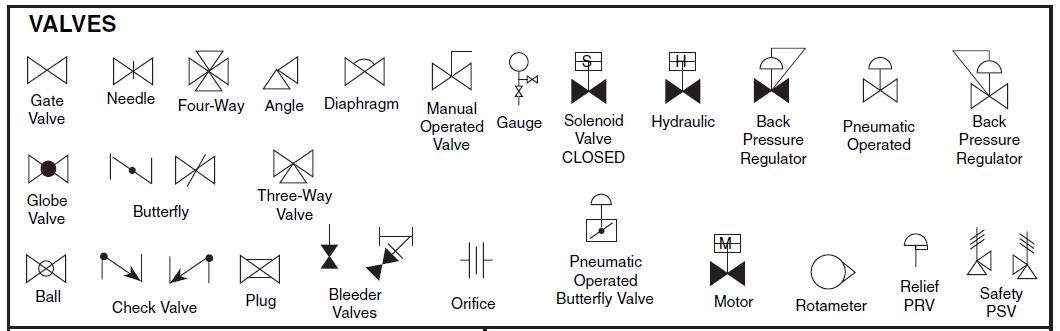
Fig. 10.1 Symbols used to represent different valves
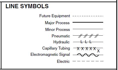
Fig. 10.2 Line symbols used to present diff purpose
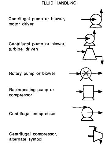 Fig. 10.3 sybols for different fluid handling equipment
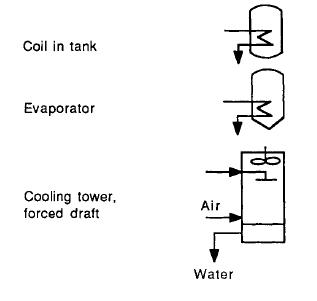
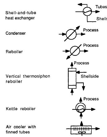
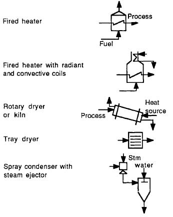
Fig. 10.4 Symbols for different heat transfer processes
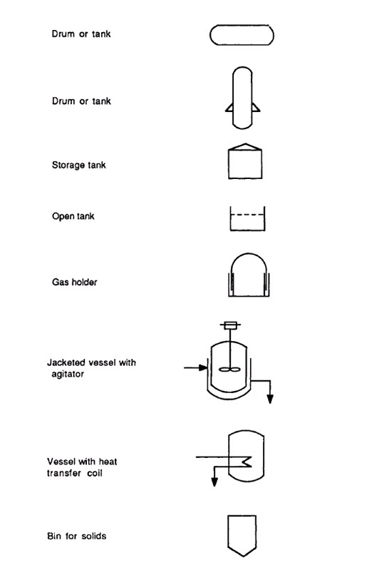
Fig. 10.6 Symbols for storage vessels
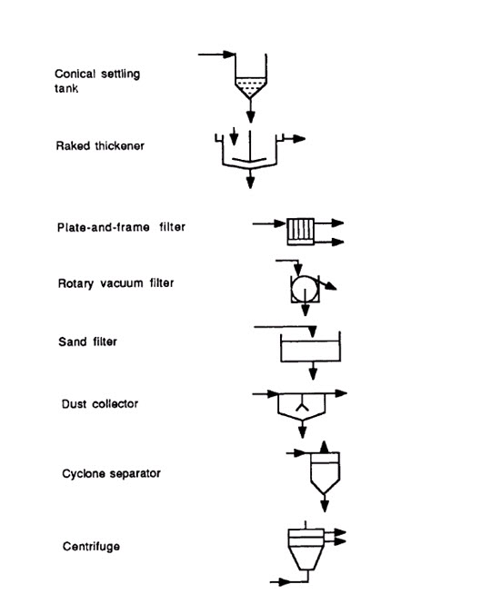
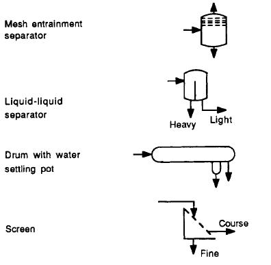
Fig. 10.8 Symbols for different separators
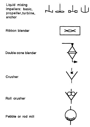
Fig. 10.9 Symbols for mixing and communition
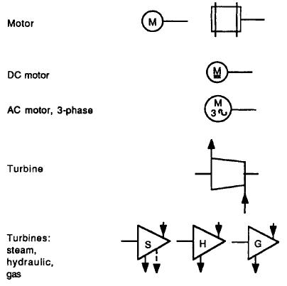
Fig. 10.10 Symbols for different drivers
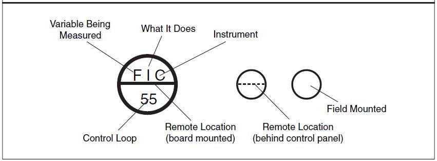
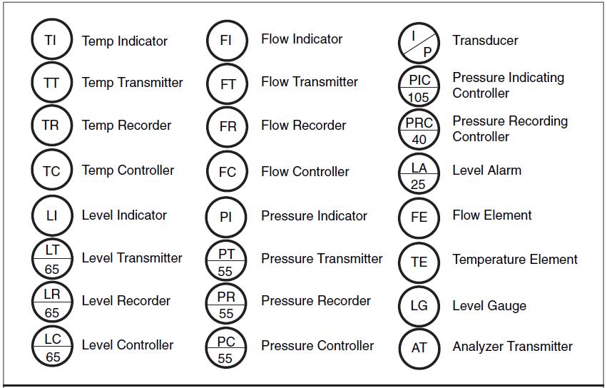
Fig. 10.11 Process control and Instrumentation Symbols
Last modified: Friday, 23 August 2013, 9:53 AM