Site pages
Current course
Participants
General
MODULE 1.
MODULE 2.
MODULE 3.
MODULE 4.
MODULE 5.
MODULE 6.
MODULE 7.
MODULE 8.
MODULE 9.
MODULE 10.
MODULE 11.
MODULE 12.
MODULE 13.
MODULE 14.
MODULE 15.
MODULE 16.
MODULE 17.
MODULE 18.
MODULE 19.
LESSON 27. Basic methods of force measurement.
Basic methods of force measurement.
Force F = MA mass x acceleration
Torque T = Force x length
Methods of force measurement
-
Balancing it against the known gravitational force as a standard mass, either directly or through a system of levers.
-
Measuring the acceleration of a body of known mass to which the unknown force is applied.
-
Balancing it against a magnetic force developed by interaction of a current carrying coil and a magnet.
-
Transducing the force to a fluid pressure and then measuring the pressure.
-
Applying the force to some elastic member and measuring the resulting deflection.
-
Measuring the change in processing of a gyroscope caused by an applied torque related to the measured force.
-
Measuring the change in natural frequency of a wire tensioned by the force.
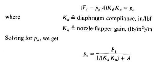
Method 1 :
Analytical balance, the pendulum scale and the platform scale.
Analytical balance : Beam is designed so that the center of mass is only slightly below the knife edge pivot and thus barely in stable equilibrium. Pendulum scale in a deflector type instrument in which the unknown force is converted to a torque that is then balanced by the torque of a fixed standard mass arranged as a pendulum.
The pendulum scale is a deflection-type instrument in which the unknown force is converted to a torque that is then balanced by the torque of a fixed standard mass arranged as a pendulum. The practical version of this principle utilizes specially shaped sectors and steel tapes to linearize the inherently nonlinear torque-angle relation of a pendulum. The unknown force Fi may be applied directly through a system of levers, such as that shown for the platform scale, to extend the range. An electrical signal proportional to force is easily obtained from any angular-displacement transducer attached to measure the angle θo.
The platform scale utilizes a system of levers to allow measurement of large forces in terms of much smaller standard weights. The beam is brought to null by a proper combination of pan weights and adjustment of the poise-weight lever arm along its calibrated scale. The scale can be made self-balancing by adding an electrical displacement pickup for null detection and an amplifier-motor system to position the poise weight to achieve null. Another interesting feature is that if a/b = c/d, the reading of the scale is independent of the location of Fi on the platform. Since this is quite convenient, most commercial scales provide this feature by use of the suspension system shown or others that allow similar results. While analytical balances are used almost exclusively for “weighing” (really determining the mass of) objects or chemical samples, platform and pendulum scales are employed also for force measurements, such as those involved in shaft power determinations with dynamometers. All three instruments are intended mainly for static force measurements.
Commercially available analytical balances may be classified as follows:
|
Description |
Range, g |
Resolution, g |
|
Macro analytical |
200 – 1,000 |
10 – 4 |
|
Semimicro analytical |
50 – 100 |
10 – 5 |
|
Micro analytical |
10 – 20 |
10 – 6 |
|
Micro balance |
less than 1 |
10 – 6 |
|
Ultramicro balance |
less than 0.01 |
10 – 7 |
Method 2
The use of an accelerometer for force measurement, is of somewhat limited application since the force determined is the resultant force on the mass. Often several unknown forces are acting, and they cannot be separately measured by this method.
Method 3
The The electromagnetic balance (method 3) utilizes a photoelectric (or other displacement sensor) null detector, an amplifier, and a torquing coil in a servo-system to balance the difference the difference between the unknown force Fi and the gravity force on a standard mass. Its advantages relative to mechanical balances are ease of use, less sensitivity to environment, faster response, smaller size, and ease of remote operation. Also, the electric output signal is convenient for continuous recording and/or automatic-control applications. Balances with built-in microprocessors allow even greater convenience, versatility, and speed of use by automating many routine procedures and providing features not formerly feasible. Automatic tare-weight systems subtract container weight from total weight to give net weight when material is placed in the container. Statistical routines allow immediate calculation of mean and standard deviation for a series of weighings. “Counting” of small parts by weighing is speeded by programming the microprocessor to read out the parts by weighing is speeded by programming the microprocessor to read out the parts count directly, rather than the weight. Accurate weighting of live laboratory animals (difficult on an ordinary balance because of animal motion) is facilitated by averaging scale readings over a preselected time. Interfacing the balance to (external to built-in) printers for permanent recording also is eased by the microprocessor.
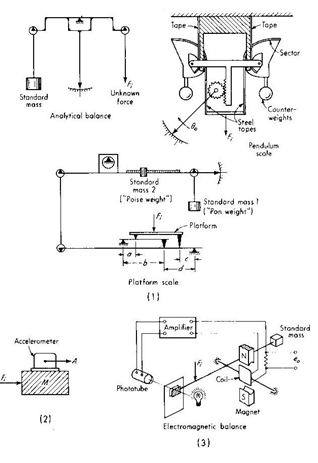
Method 4
Hydraulic cells are completely filled with oil and usually have a preload pressure of the order of 30 lb/in2. Application of load increase the oil pressure, which is read on an accurate gage. Electrical pressure transducers can be used to obtain an electrical signal. The cells are very stiff, detecting only a few thousandths of an inch under full load. Capacities to 100,000 lbf are available as standard while special units up to 10 million lbf are obtainable. Accuracy is of the order of 0.1 percent of full scale; resolution is about 0.02 percent. A hydraulic totalizer is available to produce a single pressure equal to the sum of up to 10 individual pressures in multiple-cell systems used for tank weighing, etc.,
The pneumatic load cell shown uses a nozzle-flapper transducer as a igh-gain amplifier in a servoloop. Application of force Fi causes a diaphragm deflection x, which in turn causes an increase in pressure Po since the nozzle is more nearly shut off. This increase in pressure acting on the diaphragm to its former position. For any constant Fi, the system will come to equilibrium at a specific nozzle opening and corresponding pressure Po. The static behaviour is given by,
Now Kn is not strictly constant, but varies somewhat with x, leading to a nonlinearity between x and Po. However, in practice, the product Kd Kn is very large, so that 1/(Kd Kn) is made negligible compared with A, which gives
Po = Fi / A
Which is linear since A is constant. As in any feedback system, dynamic instability limits the amount of gain that actually can be used. A typical supply pressure Ps is 60 lb/in2, and since the maximum value of Po cannot exceeded Ps , this limits Fi to somewhat less than 60A. A line of commercial pneumatic weighing systems using similar principles (combined with lever/knife-edge methods) is available in standard ranges to 110,000 lbf.
Method 5
While all the previously described force-measuring devices are intended mainly for static or slowly varying loads, the elastic deflection transducers of method 5 are widely used for both static and dynamic loads of frequency content up to many thousand hertz. While all are essentially spring-mass systems with (intentional or unintentional) damping, they differ mainly in the geometric form of “spring” employed and in the displacement transducer used to obtain an electrical signal. The displacement sensed force in terms of strain. Bonded strain gages have been found particularly useful in force measurements with elastic elements. In addition to serving as force-to-deflection transducers, some elastic elements perform the function of resolving vector forces or moments into rectangular components. As an example, the parallelogram flexure of Fig. is extremely rigid (insensitive) to all applied forces and moments except in the direction shown by the arrow. A displacement transducer arranged to measure motion in the sensitive direction thus will measure only that component of an applied vector force which lies along the sensitive axis. Perhaps the action of this flexure may be most easily visualized by considering it as a four-bar linkage with flexure hinges at the thin sections a, b, c, and d. Robotic manufacturing and assembly operations may be improved by adding various sensing functions, such as force sensing at the end of the robot’s arm. A six-axis (x, y, z force; x, y, z torque) sensor, complete with signal-processing hardware and software to interface with the robot controller, is available for connection between the robot arm and end-of-arm tooling . Simpler force sensors can also perform useful functions in robotic systems, sometimes obviating the need for expensive vision systems
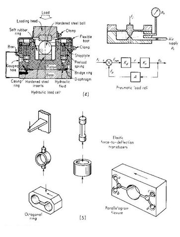
Elastic Elements For Force Measurements
Elastic elements are frequently employed to furnish an indication of the magnitude of an applied force through a displacement measurement. The simple spring is an example of this type of force-displacement transducer. In this case the force is given by
F = ky
Where k is the spring constant and y is the displacement from the equilibrium position. For the simple bar shown in Fig. the force is given by
AE
F = --------- y
L
Where A = cross-sectional area
L = length
E = Young’s modulus for the bar material
The deflection of the cantilever beam shown in Fig. is related to the loading force by
3 EI
F = ----------- y
L3
Where I is the moment of inertia of the beam about the centroidal axis in the direction of the deflection. Any one of the three devices mentioned above is suitable for use as a force transducer provided that accurate means are available for indicating the displacements. The differential transformer , for example, may be useful for measurement of these displacements, as well as capacitance and piezoelectric transducers .
Another elastic device frequently employed for force measurements is the thin ring shown in Fig.. The force-deflection relation for this type of elastic element is
16 EI
F = -------------- y
p/2 – 4/pd3
where d is the outside ring diameter and I is the moment of inertia about the centroidal axis of the ring section. The proving ring is a ring transducer that employs a sensitive micrometer for the deflection measurement, as shown in Fig.. To obtain a precise measurement, one edge of the micrometer is mounted on a vibrating reed device R, which is plucked to obtain a vibratory motion. The micrometer contact is then moved forward until a noticeable damping of the vibration is observed. Deflection measurements may be made within ±0.00002 in (0.5 µm) with this method. The proving ring is widely used as a calibration standard for large tensile-testing machines.
Last modified: Thursday, 5 December 2013, 8:13 AM