Site pages
Current course
Participants
General
MODULE 1.
MODULE 2.
MODULE 3.
MODULE 4.
MODULE 5.
MODULE 6.
MODULE 7.
MODULE 8.
MODULE 9.
MODULE 10.
MODULE 11.
MODULE 12.
MODULE 13.
MODULE 14.
MODULE 15.
MODULE 16.
MODULE 17.
MODULE 18.
MODULE 19.
LESSON 28. Torque measurement on rotating shaft.
Torque, or moment, may be measured by observing the angular deformation of a bar or hollow cylinder, as shown in Fig.. The moment is given by
πG(r4o – r4i)
M = ---------------- Ø
2L
where G = shear modulus of elasticity
ri = inside radius
ro = outside radius
L = length of the cylinder
Ø = angular deflection
strain gages attached at 45° angles as shown will indicate strains of
Mro
θ45° = ± --------------
πG(r4o – r4i)
Either the deflection or the strain measurement may be taken as an indication of the applied moment. Multiple strain gages may be installed and connected so that any deformation due to axial or transverse load is canceled out in the final readout circuit. A rather old device for the measurement of torque and dissipation of power from machines is the Prony brake. A schematic diagram is shown in Fig. Wooden blocks are mounted on a flexible band or rope, which is connected to the arm. Some arrangement is provided to tighten the rope to increase the frictional resistance between the blocks and the rotating flywheel of the machine. The torque exerted on the Prony brake is given by
T = FL
The force F may be measured by conventional platform scales or other methods discussed in the previous paragraphs.
The power dissipated in the brake is calculated from
2πTN
P = -------- hp
33,000
where the torque is in foot-pounds-force and N is the rotational speed in revolutions per minute.
TORQUE MEASUREMENT ON ROTATING SHAFTS
Measurement of the torque carried by a rotating shaft is of considerable interest for its own sake and as a necessary part of shaft power measurements. Torque transmission through a rotating shaft generally involves both a source of power and a sink (power absorber or dissipater), as in figure. Torque measurement may be accomplished by mounting either the source or the sink in bearings (“cradling”) and measuring the reaction force F and arm length L; or else the torque in the shaft itself is measured in terms of the angular twist or strain of the shaft (or a torque sensor coupled into the shaft).
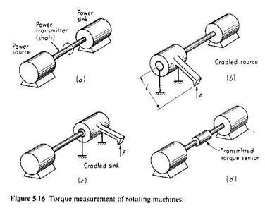
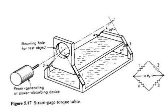
The cradling concept is the basis of most shaft power dynamometers. These are utilized mainly for measurements of steady power and torque, by using pendulum or platform scales to measure F. A free-body analysis of the cradled member reveals error sources resulting from friction in the cradle bearings, static unbalance of the cradled member, windage torque (if the shaft is rotating) , and forces due to bending and / or stretching of power lines (electric, hydraulic, etc.) attached to the cradled member. To reduce frictional effects and to make possible dynamic torque measurements, the cradle-bearing arrangement may be replaced by a flexure pivot with strain gages to sense torque, as in the above figure. The crossing point of the flexure plates defines the effective axis of rotation of the flexure pivot. Angular deflection under full load is typically less than 0.5o. This type of cross-spring flexure pivot is relatively very stiff in all directions other than the rotational one desired, just as in an ordinary bearing. The strain-gage bridge arrangement also is such as to reduce the effect of all forces other than those related to the torque being measured. Speed-torque curves for motors may be obtained quickly and automatically with such a torque sensor by letting the motor under test accelerate inertia from zero speed up to maximum while measuring speed with a dc tachometer. The torque and speed signals are applied to an XY recorder to give automatically the desired curves.
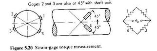
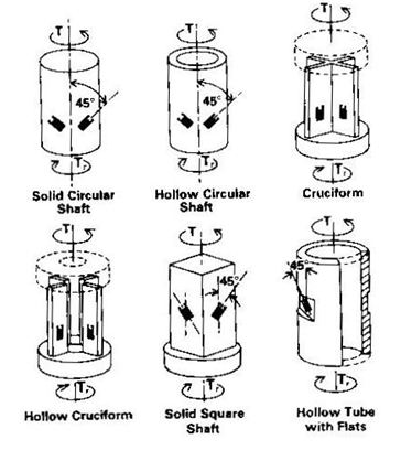
Even though they require additional equipment to transmit power and signal between rotating shaft and stationary readout, strain-gage torque sensors are very widely used. The following figure shows the basic principle. This arrangement (given accurate gage placement and matched gage characteristics) is temperature-compensated and insensitive to bending or axial stresses. The gages must be precisely at 45o with the shaft axis, and gages 1 and 3 must be diametrically opposite, as must gages 2 and 4. Accurate gage placement is facilitated by the availability of special rosettes in which two gages are precisely oriented on one sheet of backing material. In some cases the shaft already present in the machine to be tested may be fitted with strain gages. In other cases a different shaft or a commercial torquemeter must be used to get the desired sensitivity or other properties. Of the various configuration shown in the figure., one manufacturer uses the hollow cruciform for low-range units and the solid, square shaft for high-range ones. Placement of the gages on a square, rather than round, cross section of the shaft has some advantages. The gages are more easily and accurately located and more firmly bonded on a flat surface. Also, the corners of a square section in torsion are stress-free and thus provide a good location for solder joints between lead wires and gages. These joints are often a source of fatigue failure if located in a high-stress region. Also, for equivalent strain/torque sensitivity, a square shaft is much stiffer in bending than a round one, thus reducing effects of bending forces and raising shaft natural frequencies.
The torque of many machines, such as reciprocating engines, is not smooth even when the machine is running under “steady-state” conditions. If we wish to measure the average torque so as to calculate power, the higher frequency response of strain-gage torque pickups may be somewhat of a liability since the output voltage will follow the cyclic pulsations and some sort of averaging process must be performed to obtain average torque. If exceptional accuracy is not needed, the low-pass filtering effect of a dc meter used to read eo may be sufficient for this purpose. In the cradled arrangements of the following figure (employed in many commercial dynamometers for engine testing, etc.,) the inertia of the cradled member and the low-frequency response of the platform or pendulum scales used to measure F perform the same averaging function.
Commercial strain-gage torque sensors are available with built-in slip rings and speed sensors. A family of such devices covers the range 10 oz. in to 3 x 10⁶ in · lbf with full-scale output of about 40 mV. The smaller units may be used at speeds up to 24,000 r/min. Torsional stiffness of the 10 oz·in unit is 112 in·lbf / rad while a 600,000 in · lbf unit has 4.0 x 10⁶ in · lbf. Nonlinearity is 0.1 percent of full scale while temperature effect on zero is 0.002 percent of full scale / Fo and temperature effect on sensitivity is 0.002 percent / Fo over the range 70 to 170 oF .
The dynamic response of elastic deflection torque transducers is essentially slightly damped second-order, with the natural frequency usually determined by the stiffness of the transducer and the inertia of the parts connected at either end. Damping of the transducers themselves usually is not attempted, and any damping present is due to bearing friction, windage etc., of the complete test setup.
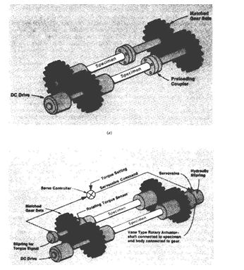
A good example of the application of torque measurement (and several other measurement system concepts of general interest) is found in a dynamic test system used in the design and development of front-wheel-drive components for automobiles (see Fig. 5.22 through 5.24). An alternative to conventional dynamometer loading systems, called the four-square principle, is utilized here to conserve energy and allow fast-response testing. Rather than connecting the shaft test specimens between a power source and a power sink, as in fig. 5.16 (an arrangement which wastes all the shaft-transmitted power sink and couples large, slow responding inertias to the specimen), the four-square principle (Fig. 5.22 a) includes a “looked-in” torque into the system by counter-twisting the flanges of a preloading coupler at assembly. Now the geared assembly can be driven at any desired speed by, say, a dc motor drive, and the shaft specimens will be subjected to the desired torque/speed conditions, but the drive supplies only friction losses (plus accelerating power if speed is changed), not the shaft-transmitted power(product of locked-in torque and shaft speed).
The basic four-square principle just described has been widely utilized for some time; however, several new features were needed in the present application. It was desired to be able to maintain a certain level of locked-in torque in the face of inevitable component wear, creep, slippage, or fatigue, which all cause a progressive “relaxation” of torque with time in the basic four-square system. Also, it was necessary to dynamically vary the locked-in torque in response to electrical commands. By replacing the mechanical preloading coupler with a rotary hydraulic actuator , measuring shaft torque with a rotating torque sensor, and driving the actuator from an electro hydraulic servo valve responding to the error between commanded and measured torque, the desired features are achieved.
To simulate actual driving conditions, the testing machine includes means for subjecting the front-wheel-drive shafts to “jounce” (up and down) motions.
Last modified: Thursday, 5 December 2013, 8:18 AM