Site pages
Current course
Participants
General
MODULE 1.
MODULE 2.
MODULE 3.
MODULE 4.
MODULE 5.
MODULE 6.
MODULE 7.
MODULE 8.
MODULE 9.
MODULE 10.
MODULE 11.
MODULE 12.
MODULE 13.
MODULE 14.
MODULE 15.
MODULE 16.
MODULE 17.
MODULE 18.
MODULE 19.
LESSON 29. BASIC METHODS OF PRESSURE MEASUREMENT
Since pressure usually can be easily transduced to force by allowing it to act on a known area, the basic methods of measuring force and pressure are essentially the same, except for the high-vacuum region where a variety of special methods not directly related to force measurement are necessary. These special methods are described in the section on vacuum measurement. Other than the special vacuum techniques, most pressure measurement is based on comparison with known deadweights acting on known areas or on the deflection of elastic elements subjected to the unknown pressure. The deadweight methods are exemplified by manometers and piston gages while the elastic deflection devices take many different forms.
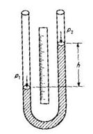
The manometer in its various forms is closely related to the piston gage, since both are based on the comparison of the unknown pressure force with the gravity force on a known mass. The manometer differs, however, in that it is self – balancing, is a deflection rather than a null instrument, and has continuous rather than stepwise output. The accuracies of deadweight gages and manometers of similar ranges are quite comparable; however, manometers become unwieldy at high pressures because of the long liquid columns involved. The U-tube manometer usually is considered the basic form and has the following relation between input and output for static conditions:
p1 – p2
h = ---------------------
pg
where g ∆ local gravity and p ∆ mass density of manometer fluid. If p2 is atmospheric pressure, than h is a direct measure of p1 as a gage pressure. Note that the cross-sectional area of the tubing (even if not uniform) has no effect. At a given location (given value of g) the sensitivity depends on only the density of the manometer fluid. Water and mercury are the most commonly used fluids. To realize the high accuracy possible with manometers, often a number of corrections must be applied. When visual reading of height h is employed, the engraved scale’s temperature expansion must be considered. The variation of p with temperature for the manometer fluid used must be corrected and the local value of g determined. Additional sources of error are found in the nonverticality of the tubes and the difficulty in reading h because of the meniscus formed by capillarity. Considerable care must be exercised in order to keep inaccuracies as small as 0.01 mm Hg for the overall measurement.
A number of practically useful variations on the basic manometer principle are shown in the following. . The cistern or well-type manometer is widely utilized because of its convenience in requiring reading of only a single leg. The well area is made very large compared with the tube; thus the zero level moves very little when pressure is applied. Even this small error is compensated by suitably distorting the length scale. However, such an arrangement, unlike a U tube, is sensitive to non uniformity of the tube cross-sectional area and thus is considered some-what less accurate.
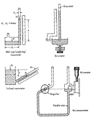
Given that manometers inherently measure the pressure difference between the two ends of the liquid column, if one end is at zero absolute pressure, then h is an indication of absolute pressure. This is the principle of the barometer . Although it is a “single-leg” instrument, high accuracy is achieved by setting the zero level of the well at the zero level of the scale before each reading is taken. The pressure in the evacuated portion of the barometer is not really absolute zero, but rather the vapor pressure of the filling fluid, mercury, at ambient temperature. This is about 10-4 lb/in2 absolute at 70oF and usually is negligible as a correction.
To increase sensitivity, the manometer may be titled with respect to gravity, thus giving a greater motion of liquid along the tube for a given vertical-height change. The inclined manometer (draft gage) exemplifies this principle. Since this is a single-leg device, the calibrated scale is corrected for the slight changes in well level so that rezeroing of the scale for each reading is not required.
The accurate measurement of extremely small pressure differences is accomplished with the micromanometer, a variation on the inclined-manometer principle. In the above figure. the instrument is initially adjusted so that when p1 = p2, the meniscus in the inclined tube is located at a reference point given by a fixed hairline viewed through a magnifier. The reading of the micrometer used to adjust well height is now noted. Application of the unknown pressure difference causes the meniscus to move off the hairline, but it can be restored to its initial position by raising or lowering the well with the micrometer. The difference in initial and final micrometer readings gives the height change h and thus the pressure. Instruments using water as the working fluid and having a range of either 10 or 20 in of water can be read to about 0.001 in of water. In another instrument in which the inclined tube (rather than the well) is moved and which uses butyl alcohol as the working fluid, the range is 2 in of alcohol, and readability is 0.0002 in. This corresponds to a resolution of 6 x 10 – 6 lb/in2.
While manometers usually are read visually by a human operator, various schemes for rapid and accurate automatic readout are available, mainly for calibration and standards work using gaseous media. The sonar manometer employs a piezoelectric transducer at the bottom of each 1.5-in-diameter glass tube to launch ultrasonic pulses, which travel up through the mercury columns, are reflected at the meniscus, and return to the bottom to be received by the transducers. The pulse from the shorter column turns on a digital counter, while that from the longer one turns it off. Thus a digital reading is obtained that is proportional to the difference in column height and thus to pressure. Resolution is 0.0003 in Hg, and accuracy is 0.001 in Hg or 0.003 percent of reading, whichever is greater. Since temperature effects on sonic velocity and column length cause additive errors, a feedback control system keeps instrument temperature at 95 ± 0.05oF.
Another instrument employs two large mercury cisterns (one fixed, one vertically movable by an electromechanical servosystem) connected by flexible tubing to create a U-tube manometer. Each cistern has a capacitor formed by a metal plate, the mercury surface, and a small air gap between them. The two capacitors are connected in an electric circuit which exhibits a null reading when they are not. This error voltage causes the servosystem to drive the movable cistern to an elevation where balance is again achieved. A digital counter on the servosystem motor shaft reads out position to the nearest 0.0001 in Hg. System accuracy is ± 0.0003 in Hg ±0.003 percent of reading. For manometers such as the two above, accessory automatic systems for generating and regulating the pressures of the gaseous (usually air or nitrogen) calibration media usually are available.
Last modified: Thursday, 5 December 2013, 8:20 AM