Site pages
Current course
Participants
General
Module 1. Average and effective value of sinusoida...
Module 2. Independent and dependent sources, loop ...
Module 3. Node voltage and node equations (Nodal v...
Module 4. Network theorems Thevenin’ s, Norton’ s,...
Module 5. Reciprocity and Maximum power transfer
Module 6. Star- Delta conversion solution of DC ci...
Module 7. Sinusoidal steady state response of circ...
Module 8. Instantaneous and average power, power f...
Module 9. Concept and analysis of balanced polypha...
Module 10. Laplace transform method of finding ste...
Module 11. Series and parallel resonance
Module 12. Classification of filters
Module 13. Constant-k, m-derived, terminating half...
LESSON 3. Independent Sources
3.1. The Circuit
Simply an electric circuit consists of three parts: (1) energy source, such as battery or generator, (2) the load or sink, such as lamp or motor, and (3) connecting wires as shown in Fig. 3.1. This arrangement represents a simple circuit. A battery is connected to a lamp with two wires. The purpose of the circuit is to transfer energy from source (battery) to the load (lamp). And this is accomplished by the passage of electrons through wires around the circuit.
The current flows through the filament of the lamp, causing it to emit visible light. The current flows through the battery by chemical action. A closed circuit is defined as a circuit in which the current has a complete path to flow. When the current path is broken so that current cannot flow, the circuit is called an open circuit.
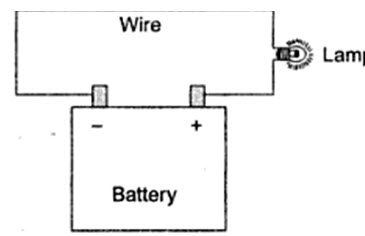
Fig.3.1
More specifically, interconnection of two or more simple circuit elements (viz. voltage sources, resistors, inductors and capacitor) is called an electric network. If a network contains at lest one closed path, it is called an electric circuit. By definition, a simple circuit element is the mathematical model of two terminal electrical devices, and it can be completely characterized by its voltage and current. Evidently then, a physical circuit must provide means for the transfer of energy.
Broadly, network elements may be classified into four groups, viz.
Active or passive
Unilateral or bilateral
Linear or nonlinear
Lumped or distributed
3.1.1. Active and Passive
Energy source (voltage or current sources are active elements, capable of delivering power to some external device. Passive elements are those which are capable only of receiving power. Some passive elements like inductors and capacitors are capable of storing a finite amount of energy, and return it later to an external element. More specifically, an active element is capable of delivering an average power greater than zero to some external device over an infinite time interval. For example, ideal sources are active elements. A passive element is defined as one that cannot supply average power that is greater than zero over an infinite time interval. Resistors, capacitors and inductors fall into this category.
3.1.2. Bilateral and Unilateral
In the bilateral element, the voltage-current relation is the same for current flowing in either direction. In contrast, a unilateral element has different relations between voltage and current for the two possible directions of current. Examples of bilateral elements are elements made of high conductivity materials in general. Vacuum diodes, silicon diodes, and metal rectifiers are examples of unilateral elements.
3.1.3. Linear and Nonlinear Elements
An element is said to be linear, if its voltage-current characteristic is all times a straight line through the origin. For example, the current passing through a resistor is proportional to the voltage applied through it, and the relation is expressed as VµI or V=IR. A liner element or network is one which satisfies the principle of superposition, i.e. the principle of homogeneity and additivity. An element which does not satisfy the above principle is called a nonlinear element.
3.1.4. Lumped and Distributed
Lumped elements are those elements which are very small in size and in which simultaneous actions takes place for any given cause at the same instant of time. Typical lumped elements are capacitors, resistors, inductors and transformers. Generally the elements are considered as lumped when their size is very small compared to the wave length of the applied signal. Distributed elements, on the other hand, are those which are not electrically separable for analytical purposes. For example, a transmission line which has distributed resistance, inductance and capacitance along its length may extend for hundreds of miles.
3.2 Independent sources
The source which does not depends on other voltages or currents in the network for their value. These are represented by a circle with a polarity of voltage or direction of current indicated inside
Energy Sources
According to their terminal voltage-current characteristics, electrical energy sources are categorized into ideal voltage sources and ideal current sources. Further they can be divided into independent and dependent sources.
An ideal voltage source is a two-terminal element in which the voltage vs is completely independent of the current is through its terminals. The representation of ideal constant voltage source is shown in Fig.3.2 (a).
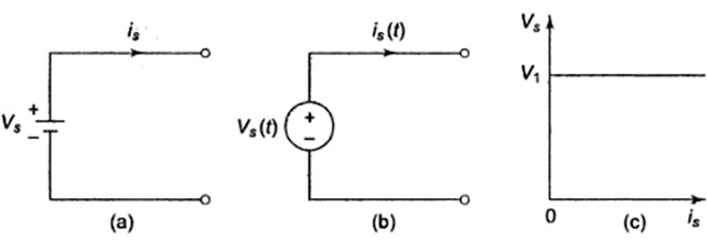
Fig. 3.2
If we observe the v=I characteristics for an ideal voltage source as shown in Fig.3.2 (c) at any time, the value of the terminal voltage vs is constant with respect to the value of current is. Whenever vs = 0, the voltage source is the same as that of a short circuit. Voltage sources need not have constant magnitude; in many cases the specified voltage may be time-dependent like a sinusoidal waveform. This may be represented as shown in Fig.3.2 (b). In many practical voltage sources, the internal resistance is represented in series with the source as shown in Fig.3.3 (a). In this, the voltage across the terminals falls as the current through it increases, as shown in Fig. 3.3 (b).
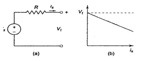
Fig. 3.3
The terminal voltage vt depends on the source current as shown in Fig. 3.3(b), where vt = vs – I, R.
An ideal constant current source is a two-terminal element in which the current is completely independent of the voltage vs across its terminals. Like voltage sources we can have current sources of constant magnitude is or sources whose current varies with time is(t). The representation of an ideal current source is shown in Fig.3.4 (a).
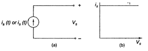
Fig.3.4
If we observe the v – i characteristics for an ideal current source as shown in Fig.3.4 (b), at any time the value of the current is is constant with respect to the voltage across it. In many practical current sources, the resistance is in parallel with a source as shown in Fig. 3.5 (a). In this the magnitude of the current falls as the voltage across its terminals increases. Its terminal v – i characteristic is shown in Fig. 3.5 (b). The terminal current is given by it – is – (vs/R), where R is the internal resistance of the ideal current source.
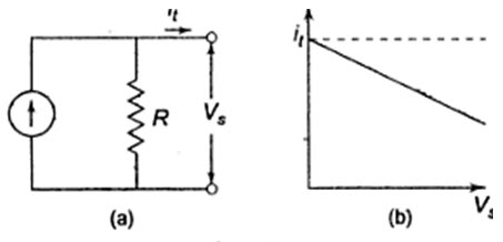
Fig.3.5
The two types of ideal sources we have discussed are independent sources for which voltage and current are independent and are not affected by other parts of the circuit. In the case of dependent sources, the source voltage or current is not fixed, but is dependent on the voltage or current existing at some other location in the circuit.