Site pages
Current course
Participants
General
Module 1. Average and effective value of sinusoida...
Module 2. Independent and dependent sources, loop ...
Module 3. Node voltage and node equations (Nodal v...
Module 4. Network theorems Thevenin’ s, Norton’ s,...
Module 5. Reciprocity and Maximum power transfer
Module 6. Star- Delta conversion solution of DC ci...
Module 7. Sinusoidal steady state response of circ...
Module 8. Instantaneous and average power, power f...
Module 9. Concept and analysis of balanced polypha...
Module 10. Laplace transform method of finding ste...
Module 11. Series and parallel resonance
Module 12. Classification of filters
Module 13. Constant-k, m-derived, terminating half...
LESSON 4. Dependent sources
4.1 Dependent or controlled sources are of the following types
(i) Voltage controlled voltage source (VCVS)
(ii) Current controlled voltage source (CCVS)
(iii) Voltage controlled current source (VCCS)
(iv) Current controlled current source (CCCS)
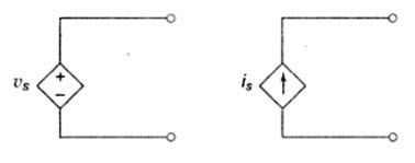
Fig. 4.1
These are represented in a circuit diagram by the symbol shown in Fig.4.1. These types sources mainly occur in the analysis of equivalent circuits of transistors.
4.2. Kirchhoff’s Voltage Law
Kirchhoff’s voltage law states that the algebraic sum of all branch voltages around any closed path in a circuit is always zero at all instants of time. When the current passes through a resistor, there is a loss of energy and therefore, a voltage drop. In any element, the current always flows from higher potential to lower potential. Consider to circuit in Fig.4.2. It is customary to take the direction of current I as indicated in the figure, i.e. it leaves the positive terminal of the voltage source and enters into the negative terminal.
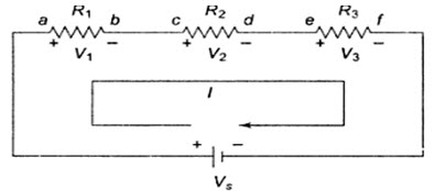
Fig. 4.2
As the current passes through the circuit, the sum of the voltage drop around the loop is equal to the total voltage in that loop. Here the polarities are attributed to the resistors to indicate that the voltages at points a, c and e are more than the voltages at b, d and f, respectively, as the current passes from a to f.
Vs=V1+V2+V3
Consider the problem of finding out the current supplied by the source V in the circuit shown in Fig. 4.3.
Our first step is to assume the reference current direction and to indicate the polarities for different elements. (See Fig.4.4).
By using Ohm’s law, we find the voltage across each resistors as follows.
VR1=IR1, VR2 = IR2, VR3 = IR3
where VR1, VR2 and VR3 are the voltages across R1, R2 and R3, respectively. Finally, by applying Kirchhoff’s law, we can form the equation.
V = VR1 + VR2 + VR3
V = IR1 + IR2 + IR3
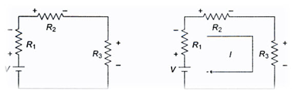
Fig.4.3 Fig. 4.4
From the above equation the current delivered by the source is given by
\[I={V \over {{R_1} + {R_2} + {R_3}}}\]
4.3. Voltage Division
The series circuit acts as a voltage divider. Since the same current flows through each resistor, the voltage drops are proportional to the values of resistors. Using this principle, different voltages can be obtained from a single source, called a voltage divider. For example, the voltage across a 40 W resistor is twice that of 20 W in a series circuit shown in Fig. 4.5
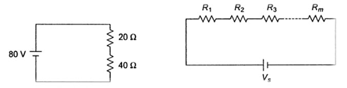
Fig.4.5 Fig.4.6
In general, if the circuit consists of a number of series resistors, the total current is given by the total voltage divided by equivalent resistance. This is shown in Fig. 4.6.
The current in the circuit is given by I = Vs/(R1+R2+…+Rm). The voltage across any resistor is noting but the current passing through it, multiplied by that particular resistor.
Therefore, VR1 = IR1
VR2 = IR2
VR3 = IR3
VRm = IRm
or \[{V_{Rm}}={{{V_s}\left( {{R_m})} \right)} \over {{R_1} + {R_2} + ... + {R_m}}}\]
From the above equation, we can say that the voltage drop across any resistor or a combination of resistors, in a series circuit is equal to the ratio of that resistance value to the total resistance, multiplied by the source voltage, i.e.
\[{V_m}={{{R_m}} \over {{R_T}}}{V_s}\]
where Vm is the voltage across mth resistor, Rm is the resistance across which the voltage is to be determined and RT is the total series resistance.
4.4. Power in a Series Circuit
The total power supplied by the source in any series resistive circuit is equal to the sum of the powers in each resistor in series, i.e.
Ps = P1+P2+P3+….+Pm
Where m is the number of resistors in series, Ps is the total power supplied by source and Pm is the power in the last resistor in series. The total power in the series circuit is the total voltage applied to a circuit, multiplied by the total current. Expressed mathematically,
\[{V_m}={{{R_m}} \over {{R_T}}}{V_s}\]
where Vs is the total voltage applied, RT is the total resistance, and I is the total current.
4.5. Kirchhoff’s Current Law
Kirchhoff’s current law states that the sum of the currents entering into any node is equal to the sum of the currents leaving that node. The node may be an interconnection of two or more branches. In any parallel circuit, the node is a junction point of two or more branches. The total current entering into a node is equal to the current leaving that node. For example, consider the circuit shown in Fig.4.7, which contains two nodes A and B.
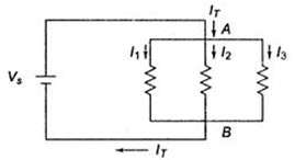
Fig.4.7
The total current I1, I2 and I3. These currents flow out of node A. According to Kirchhoff’s current law, the current into node A is equal to the total current out of node A: that is, IT = I1+I2+I3. If we consider node B, all three currents I1, I2, I3 are entering B, and the total current IT is leaving node B, Kirchhoff’s current law formula at this node is therefore the same as at node A.
I1+I2+I3 = IT
In general, sum of the currents entering any point or node or junction equal to sum of the currents leaving from that point or node or junction as shown in Fig.4.8.
I1 + I2 + I4 + I7 = I3 + I5 + I6
If all of the terms on the right side are brought over to the left side, their signs change to negative and a zero is left on the right side, i.e.
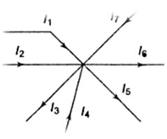
Fig.4.8
I1 + I2 + I4 + I7 - I3 - I5 - I6 = 0
This means that the algebraic sum of all the currents meeting at a junction is equal to zero.
4.6. Parallel Resistance
When the circuit is connected in parallel, the total resistance of the circuit decreases as the number of resistors connected in parallel increases. If we consider m parallel branches in a circuit as shown in Fig.4.8, the current equation is
IT = I1 + I2 + … + Im
The same voltage is applied across each resistor. By applying Ohm’s law, the current in each branch is given by
\[{I_1}={{{V_s}} \over {{R_1}}},\,{I_2} = {{{V_s}} \over {{R_2}}},.....{I_m}={{{V_s}} \over {{R_m}}}\]
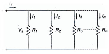
Fig. 4.9
According to Kirchhoff’s current law,
IT = I1 + I2 + I3+ … + Im
\[{{{V_s}} \over {{R_T}}} = {{{V_s}} \over {{R_1}}} + {{{V_s}} \over {{R_2}}} + {{{V_s}} \over {{R_3}}} + ... + {{{V_s}} \over {{R_m}}}\]
From the above equation, we have
\[{1 \over {{R_T}}}={1 \over {{R_1}}} + {1 \over {{R_2}}} + ... + {{{V_s}} \over {{R_m}}}\]
4.7. Current Division
In a parallel circuit, the current divides in all branches. Thus, a parallel circuit acts as a current divider. The total current entering into the parallel branches is divided into the braches currents according to the resistance values. The branch having higher resistance allows lesser current, and the branch with lower resistance allows more current. Let us find the current division in the parallel circuit shown in Fig. 4.10.

Fig. 4.10
The voltage applied across each resister is Vs. The current passing through each resistors is given by
\[{I_1}={{{V_S}} \over {{R_1}}},\,{I_2}={{{V_s}} \over {{R_2}}}\]
If R1 is the total resistance, which is given by R1R2/ (R1+R2),
Total current \[{I_T}={{{V_S}} \over {{R_T}}}={{{V_s}} \over {{R_1}{R_2}}}\left( {{R_1} + {R_2}} \right)\]
or \[{I_T}={{{I_1}{R_1}} \over {{R_1}{R_2}}}\left( {{R_1} + {R_2}} \right)\,\sin ce\,\,\,{V_s}\,=\,{I_1}{R_1}\]
\[{I_1}={I_T}={{{R_2}} \over {{R_1} + {R_2}}}\]
Similarly, \[{I_2}={I_T}.{{{R_1}} \over {{R_1} + {R_2}}}\]
From the above equations, we can conclude that the current in any branch is equal to the ratio of the opposite branch resistance to the total resistance value, multiplied by the total current in the circuit. In general, if the circuit consists of m branches, the current in any branch can be determined by
\[{I_i}={{{R_T}} \over {{R_i} + {R_T}}}{I_T}\]
where Ii represents the current in the ith branch
Ri is the resistance in the ith branch
RT is the total parallel resistance to the ith branch and
IT is the total current entering the circuit.
4.8. Power in a Parallel Circuit
The total power supplied by the source in any parallel resistive circuit is equal to the sum of the powers in each resistor in parallel , i.e.
PS = P1 + P2 + P3 + … + Pm
where m is the number of resistors in parallel, PS is the total power and Pm is the power in the last resistor.
Last modified: Wednesday, 25 September 2013, 9:32 AM