Site pages
Current course
Participants
General
Module 1. Dairy Development in India
Module 2. Engineering, thermal and chemical proper...
Module 3. Unit operation of various dairy and food...
Module 4. Working principles of equipment for rece...
Module 5. Dairy plant design and layout, compositi...
Module 6. Deterioration in products and their cont...
Module 7. Physical, chemical and biological method...
Module 8. Changes undergone by the food components...
Module 9. Plant utilities requirement.
References
Lesson 11. Pasteurization of Milk
11. Introduction
The process of pasteurization was named after Louis Pasteur, who discovered method of inactivating spoilage organisms in wine by applying heat at temperatures below its boiling point. The process was later applied to milk and remains the most important operation in the processing of milk.
11.1 Definition (FSSAI, 2006):
The terms ―Pasteurisation, ―Pasteurised and similar terms shall be taken to refer to the process of heating every particle of milk of different classes to at least 630C and holding at such temperature continuously for at least 30 minutes or heating it to at least 71.50C and holding at such temperature continuously for at least 15 seconds or an approved temperature time combination that will serve to give a negative Phosphatase Test.
All pasteurised milk of different classes shall be cooled immediately to a temperature of 100C, or less
11.2 Purpose:
There are two distinct purposes for the process of milk pasteurization:
11.2.1 Public Health Aspect - to make milk and milk products safe for human consumption by destroying all bacteria that may be harmful to health (pathogens)
11.2.2 Keeping Quality Aspect - to improve the keeping quality of milk and milk products. Pasteurization can destroy some undesirable enzymes and many spoilage bacteria. Shelf life can be 7, 10, 14 or up to 16 days. The extent of microorganism inactivation depends on the combination of temperature and holding time. Minimum temperature and time requirements for milk pasteurization are based on thermal death time studies for the most heat resistant pathogen found in milk, Coxiella Burnetii.
11.3 Methods of Pasteurization
There are two basic methods, batch and continuous.
11.3.1 Batch method
The milk or milk products is heated and cooled in one, two or some times more than that tanks. The process involves heating every particle of milk atleast to the temperature of 63 oC for 30 min, and cooled rapidly to below 10 oC.
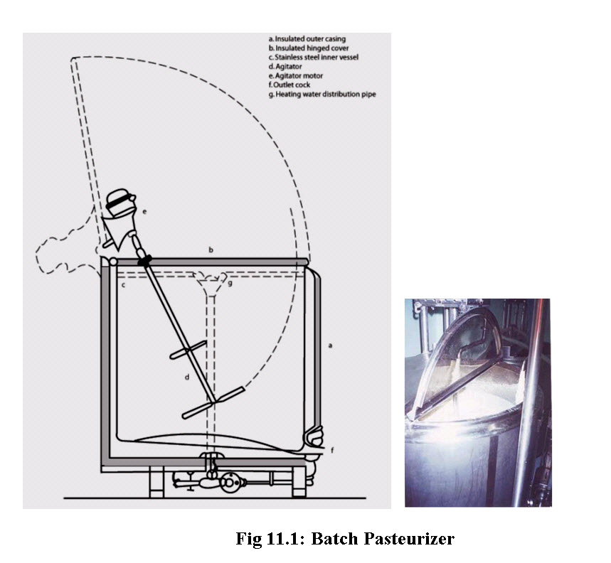
The parts of a typical batch pasteurizer are following:
Insulated outer casing
Insulated hinged cover
Stainless steel inner vessel
Agitator and its motor
Outlet cock and heating water distribution pipe.
This system is well suited for small-scale operation, where less than 3000 to 5000 litres of milk are available. The vat may be rectangular, but a vertical, cylindrical design is preferred for practical reasons. The vat normally consists of an inner vessel, surrounded by an insulated outer casting, thus forming a jacket, through which hot water or steam is passed (Figure 11.1). After the milk has reached the required temperature (63.0°C), it is usually held at that temperature for a certain fixed period (30 minutes). Thereafter, it is cooled as quickly as possible either by circulating refrigerant/chilled water or through plate/surface chiller. Cooling the milk after pasteurization by circulating a refrigerant – in most cases cold water through the jacket or the vat may take much time. Therefore, a separate small capacity surface, tubular or plate cooler may be used to rapidly cool the milk to the required temperature. This system also has the advantage that the vat will be available sooner for the pasteurization of another batch of milk.
Batch pasteurizers have a small heating surface area relative to their contents. Heat transfer is greatly improved by agitating the milk. Agitators of different design are used for this purpose. They may even consist of double-walled paddles or other devices with internal steam or water circulation. Care must be taken to avoid foam formation during filling of vat. It is very difficult to heat the milk and foam together uniformly and consequently microorganisms present in the foam may survive pasteurization. If the inlet valve is at the bottom of the vat, foam formation can easily be prevented. A lid or cover on top of the vat promotes a uniform temperature of the contents and prevents skin formation on the milk
11.3.2 Continuous Method
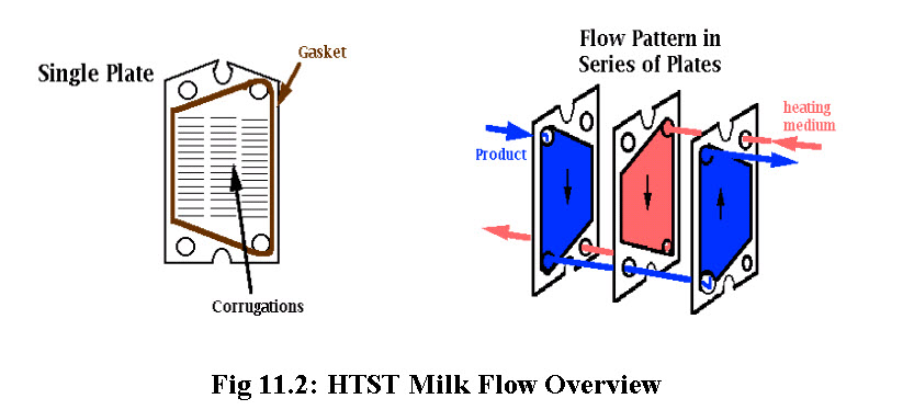
Continuous method has several advantages over the batch method, the most important being time and energy saving. For continuous processing, a high temperature short time (HTST) pasteurizer is used. The heat treatment is accomplished using a plate heat exchanger. This piece of equipment consists of a stack of corrugated stainless steel plates clamped together in a frame. There are several flow patterns that can be used. Gaskets are used to define the boundaries of the channels and to prevent leakage. The heating medium can be vacuum steam or hot water.
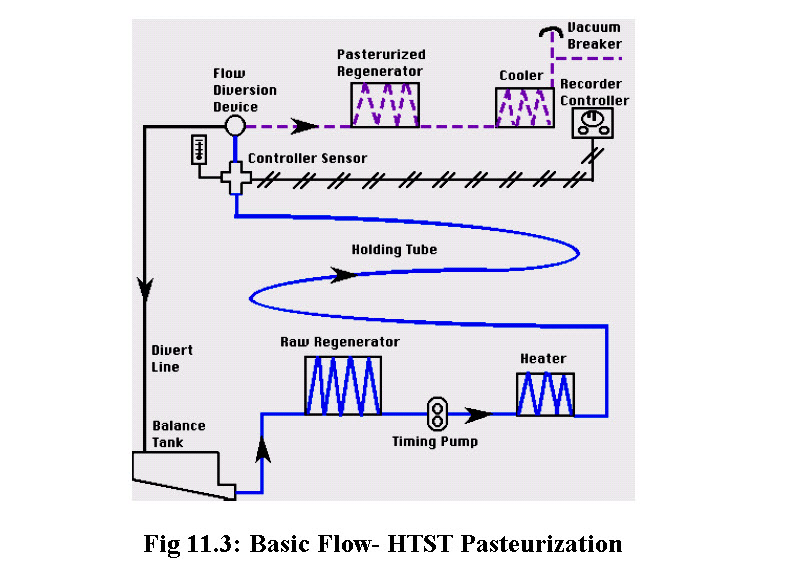
Cold raw milk at 4° C in a constant level tank is drawn into the regenerator section of pasteurizer. Here it is warmed to approximately 57°C - 68°C by heat given up by hot pasteurized milk flowing in a counter current direction on the opposite side of thin, stainless steel plates. The raw milk, still under suction, passes through a positive displacement timing pump which delivers it under positive pressure through the rest of the HTST system.
The raw milk is forced through the heater section where hot water on opposite sides of the plates heat milk to a temperature of at least 72° C. The milk, at pasteurization temperature and under pressure, flows through the holding tube where it is held for at least 16 sec. The maximum velocity is governed by the speed of the timing pump, diameter and length of the holding tube and surface friction. After passing temperature sensors of an indicating thermometer and a recorder-controller at the end of the holding tube, milk passes into the flow diversion valve (FDV). The FDV assumes a forward-flow position if the milk passes the recorder-controller at the pre-set cut-in temperature (>72° C). The FDV remains in normal position which is in diverted-flow if milk has not achieved pre-set cut-in temperature. The improperly heated milk flows through the diverted flow line of the FDV back to the raw milk constant level tank.
Properly heated milk flows through the forward flow part of the FDV to the pasteurized milk regenerator section where it gives up heat to the raw product and in turn is cooled to approximately 32° C - 9° C. The warm milk passes through the cooling section where it is cooled to 4° C or below by coolant on the opposite sides of the thin, stainless steel plates. The cold, pasteurized milk passes through a vacuum breaker at least 12 inches above the highest raw milk in the HTST system then on to storage tank filler for packaging.
11.3.2.1 Holding Time
When fluids move through a pipe, either of two distinct types of flow can be observed. The first is known as turbulent flow which occurs at high velocity and in which eddies are present moving in all directions and at all angles to the normal line of flow. The second type is streamline, or laminar flow which occurs at low velocities and shows no eddy currents. The Reynolds number, is used to predict whether laminar or turbulent flow will exist in a pipe:
Re < 2100 laminar
Re > 4000 fully developed turbulent flow
There is an impact of these flow patterns on holding time calculations and the assessment of proper holding tube lengths. The holding time is determined by timing the interval for an added trace substance (salt) to pass through the holder. The time interval of the fastest particle of milk is desired. Thus the results found with water are converted to the milk flow time by formulation since a pump may not deliver the same amount of milk as it does water.
11.3.2.2 Pressure Differential
For continuous pasteurizing, it is important to maintain a higher pressure on the pasteurized side of the heat exchanger. By keeping the pasteurized milk at least 1 psi higher than raw milk in regenerator, it prevents contamination of pasteurized milk with raw milk in event that a pin-hole leak develops in thin stainless steel plates. This pressure differential is maintained using a timing pump in simple systems, and differential pressure controllers and back pressure flow regulators at the chilled pasteurization outlet in more complex systems. The position of the timing pump is crucial so that there is suction on the raw regenerator side and pushes milk under pressure through pasteurized regenerator. There are several other factors involved in maintaining the pressure differential:
The balance tank overflow level must be less than the level of lowest milk passage in the regenerator
Properly installed booster pump is all that is permitted between balance tank and raw regenerator
No pump after pasteurized milk outlet to vacuum breaker
There must be greater than a 12 inch vertical rise to the vacuum breaker
The raw regenerator drains freely to balance tank at shut-down
11.3.2.3 Basic Component Equipment of HTST Pasteurizer
11.3.2.3.1 Balance Tank
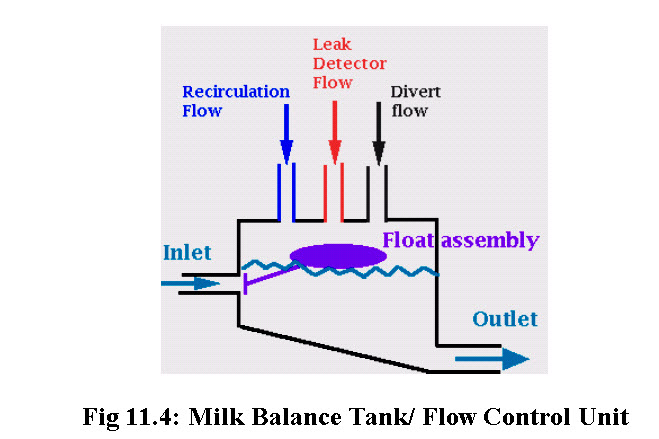
The balance or constant level tank provides a constant supply of milk. It is equipped with a float valve assembly which controls the liquid level nearly constant ensuring uniform head pressure on the product leaving the tank. The overflow level must always be below the level of lowest milk passage in regenerator. It, therefore, helps to maintain a higher pressure on the pasteurized side of the heat exchanger. The balance tank also prevents air from entering the pasteurizer by placing the top of the outlet pipe lower than the lowest point in the tank and creating downward slopes of at least 2%. The balance tank provides a means for recirculation of diverted or pasteurized milk.
11.3.2.3.2 Regenerator
Heating and cooling energy can be saved by using a regenerator which utilizes the heat content of the pasteurized milk to warm the incoming cold milk. Its efficiency may be calculated as follows:
% regeneration = temp. increase due to regenerator/total temp. increase
For example: Cold milk entering system at 4° C, after regeneration at 65° C, and final temperature of 72° C would have an 89.7% regeneration:
65 – 4
-------- = 89.7
72 - 4
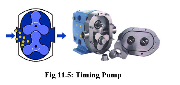
11.3.2.3.3 Timing pump
The timing pump draws product through the raw regenerator and pushes milk under pressure through pasteurized regenerator. It governs the rate of flow through the holding tube. It must be a positive displacement pump equipped with variable speed drive that can be legally sealed at the maximum rate to give minimum holding time in holding tubes. It also must be interwired so it only operates when FDV is fully forward or fully diverted, and must be "fail-safe". A centrifugal pump with magnetic flow meter and controller may also be used.
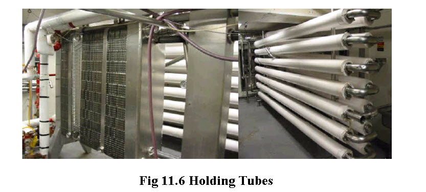
11.3.2.3.4 Holding tube
Must slope upwards 1/4"/ft. in direction of flow to eliminate air entrapment so nothing flows faster at air pocket restrictions.
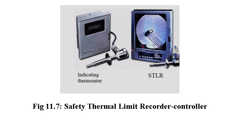
11.3.2.3.5 Indicating thermometer
The indicating thermometer is considered the most accurate temperature measurement. It is the official temperature to which the safety thermal limit recorder (STLR) is adjusted. The probe should sit as close as possible to STLR probe and be located not greater than 18 inches upstream of the flow diversion device.
11.3.2.3.6 Safety Thermal Limit Recorder-controller (STLR)
The STLR records the temperature of the milk and the time of day. It monitors, controls and records the position of the flow diversion Valve (FDV) and supplies power to the FDV during forward flow. There are both pneumatic and electronic types of controllers. The operator is responsible for recording the date, shift, equipment, ID, product and amount, indicating thermometer temperature, cleansing cycles, cut in and cut out temperatures, any connects for unusual circumstances, and his/her signature.
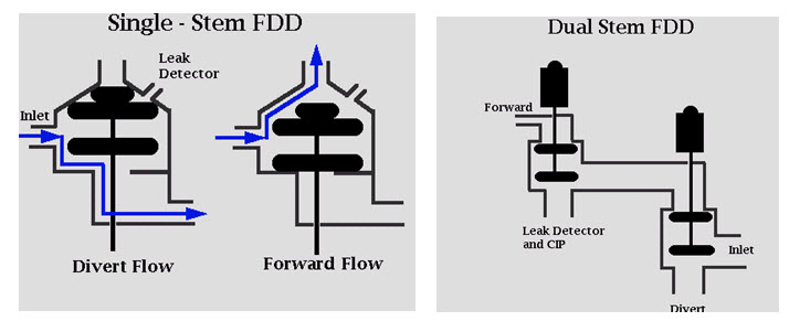
11.3.2.3.7 Flow Diversion Valve (FDV)
Also called the flow diversion Device (FDD), it is located at the downstream end of the upward sloping holding tube. It is essentially a 3-way valve, which, at temperatures greater than 72° C,opens to forward flow. This step requires power. At temperatures less than 72° C, the valve recloses to the normal position and diverts the milk back to the balance tank. It is important to note that the FDV operates on the measured temperature, not time, at the end of the holding period. There are two types of FDV:
single stem - an older valve system that has the disadvantage that it can't be cleaned in place.
dual stem - consists of 2 valves in series for additional fail safe systems. This FDV can be cleaned in place and is more suited for automation.
11.3.2.3.8 Vacuum Breaker
At the pasteurized product discharge is a vacuum breaker which breaks to atmospheric pressure. It must be located greater than 12 inches above the highest point of raw product in system. It ensures that nothing downstream is creating suction on the pasteurized side.
11.3.2.4 Auxiliary Equipment
11.3.2.4.1 Booster Pump
It is centrifugal "stuffing" pump which supplies raw milk to the raw regenerator for the balance tank. It must be used in conjunction with pressure differential controlling device and shall operate only when timing pump is operating, proper pressures are achieved in regenerator, and system is in forward flow.
11.3.2.4.2 Automated Public Health Controllers
These systems are used for time and temperature control of HTST systems. There are concerns that with sequential control, the critical control points (CCP's) are not monitored all the time; if during the sequence it got held up, the CCP's would not be monitored. With operator control, changes can be made to the program which might affect CCP's; the system is not easily sealed. No computer program can be written completely error free in large systems; as complexity increases, so too do errors. This gives rise to a need for specific regulations or computer controlled CCP's of public health significance:
1. Dedicated computer - no other assignments, monitor all CCP's at least once/sec
2. Not under control of any other computer system or override system, i.e., network
3. Separate computer on each pasteurizer
4. I/O bus for outputs only, to other computers no inputs from other computers
5. On loss of power - public health computers should revert to fail safe position (e.g. divert)
6. Last state switches during power up must be fail safe position
7. Programs in ROM - tapes/disks not acceptable
8. Inputs must be sealed, modem must be sealed, program sealed
9. No operator override switches
10. Proper calibration procedure during that printing - Public health computer must not leave public health control for > 1 sec and upon return must complete 1 full cycle before returning to printing
11. FDV position must be monitored and temperature in holding tube recorded during change in FDV position
12. Download from ROM to RAM upon startup
13. Integrated with CIP computer which can be programmed e.g., FDV, booster pump controllable by CIP computer when in CIP made only.
Last modified: Thursday, 22 August 2013, 6:03 AM