Site pages
Current course
Participants
General
Module 1:Water Resources Utilization& Irrigati...
Module 2:Measurement of Irrigation Water
Module 3: Irrigation Water Conveyance Systems
Module 4: Land Grading Survey and Design
Module 5: Soil –Water – Atmosphere Plants Intera...
Module 6: Surface Irrigation Methods
Module 7: Pressurized Irrigation
Module 8: Economic Evaluation of Irrigation Projec...
19 April - 25 April
26 April - 2 May
LESSON 9 Water Flow Measurement in Pipes
In the previous lesson, we have studied methods for water flow measurements in open channel. However, irrigation water also conveyed through pipes and therefore we will now study methods of flow measurements in pipes.
9.1 Difference between Pipe Flow and Open Channel Flow
|
Open Channel Flow |
Pipe Flow |
|
|
|
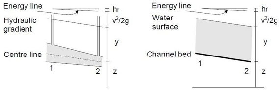
Fig. 9.1. Pipe flow (left) and open channel flow (right).
(Source:http://www.efm.leeds.ac.uk/CIVE/CIVE2400/OpenChannelHydraulics2.pdf, accessed on 05/06/2012)
From the above Fig. 9.1 we can see that the in the pipe flow there is a pressure equal to a head y whereas in the open channel the surface is at atmospheric pressure. denotes the head loss from section 1 to section 2.In case of open channel the conditions are much more varied than pipe flow in terms of surface geometry, surface roughness, depth and velocity of flow anuniformity of flow.
9.2 Venturimeter
9.2.1 Definition: Aventurimeter is a device used to measure the rate of flow of a fluid through a pipe and is often fixed permanently at different sections of the pipeline to know the discharge there.
9.2.2 Description:Venturimeter consists of three parts:
-
A short converging part
-
A throat
-
A diverging part
Due to the constriction there is an increase in the flow velocity and hence an increase in the kinetic energy. In the venturimeter (Fig.9.2) the fluid is accelerated through a converging cone of angle 15-20° and the pressure difference between the upstream side of the cone and the throat is measured and provides the signal for the rate of flow.
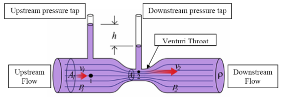
Fig.9.2.Venturimeter and its operations.
(Source:http://fetweb.ju.edu.jo/ME/courses/labs/measurements/labsheet/Experiment%20No%203%20flow%20measurements.pdf
The fluid slows down in a cone with smaller angle (5-7°) where most of the kinetic energy is converted back to pressure energy. Because of the cone and the gradual reduction in the area there is no "vena contracta". The flow area is at minimum at the throat.
9.2.3 Principle of Operation
It works on the Bernoulli’s principle. From Bernoulli’s principle the increase in kinetic energy gives rise to a reduction in pressure. Rate of discharge from the constriction can be calculated knowing the pressure reduction across the constriction, area of cross-section, density of fluid and the coefficient of discharge, . Coefficient of discharge is the ratio of actual flow to the calculated flow and it takes into account the stream contraction and frictional effects.
For measuring discharge we should apply Bernoulli’s equation at point 1 and at point 2 (Fig.9.2).The following treatment is limited to incompressible fluids.Friction is neglected, the meter is assumed to be horizontal and there is no pump. If and are the average velocities at point 1 and point 2 respectively and ρ is the density of fluid, then Bernoulli’s equation can be written as
![]() .......(9.1)
.......(9.1)
Where,
P1 = P2 pressure at section 1 and 2
Since Z1 =Z2 ,
![]() ......(9.2)
......(9.2)
Now applying the equation of continuity at both points, we have
A1 v1 = A2 v1 (9.3)
![]() .......(9.4)
.......(9.4)
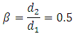
Where d1, d2 and are the diameters at point 1(pipe) and at point 2(throat) respectively.
Now putting the value of in equation (2) and if
![]()
we have
![]() ............(9.5)
............(9.5)
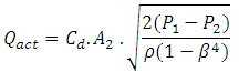
To account for the friction losses a coefficient of discharge, is introduced in the above equation and the final equation becomes:
![]() ...........(9.6)
...........(9.6)
depends upon the type of flow, type of fluid and dimensions of venture tube and pipe.
Given below are the formulae to calculate the value of head difference in terms of the liquid flowing through the venturi from the head difference observed in the manometric liquid:
1. When the manometric liquid is heavier than the liquid flowing through the pipe:
![]() ........(9.7)
........(9.7)
2. When the manometric liquid is lighter than the liquid flowing in the pipe:
![]() .......(9.8)
.......(9.8)
Where,
h = head difference in terms of the liquid flowing in the pipe
x = head difference in the manometer
Sh = specific gravity of the liquid flowing in the pipe
So = specific gravity of the manometric liquid
Merit:
- Widely used particularly for large volume liquid and gas flows.
Demerits:
- Highly expensive
- Occupies considerable space
- Cannot be altered for measuring pressure beyond a maximum velocity.
Example 9.1:
A horizontal venturimeter with inlet and throat diameters 36 cm and 18 cm respectively is used to measure the flow of water. The reading of the differential manometer connected to the inlet and the throat is 15 cm of mercury. Determine the rate of flow. Take Cd = 0.98.
Solution:
Given
Diameter at inlet, d1 = 36 cm
Diameter at throat, d2 = 18 cm
![]()
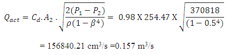
From equation (6) we know:
We know that, ![]()
Calculating h from equation (7)
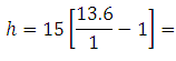 189.0 cm of water
![]()
Putting the values in equation (6):
9.3 Pitot Tube
9.3.1 Definition
It a device to measure the fluid flow velocity at any point in a pipe or channel.
9.3.2 Description
In its simplest form the pitot tube consists of a glass tube bent at right angles.

Fig.9.3.Pitot tube.(Source: Bansal, 2005,)
9.3.3 Principle of Operation
The velocity calculation is done by measuring the stagnation pressure and then applying the Bernoulli’s theorem, the basic working principle being the conversion of kinetic energy to pressure energy at the point where velocity becomes zero.
Applying Bernoulli’s theorem at points 1 and 2 shown in Fig.9.3.
![]() ........(9.9)
........(9.9)
The symbols have same meaning as in case of venturimeter.
As Z1 = Z2 and v2 = 0
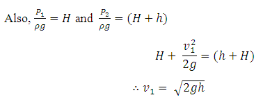 .........(9.10)
This gives the theoretical velocity. The actual velocity is given by:
![]() ...... (9.11)
...... (9.11)
Where,
h = height to which the liquid rises above the pipe.
Cv= the co-efficient of pitot tube.
Merits:
- Simple in construction having no moving parts.
- Easy to install.
- Requires no external power source.
- Easy measurement and velocity.
Demerits:
- Can’t be used for turbulent flow, i.e. only used for laminar flow.
- Less accurate in measurement of velocity due to assumption of ideal fluid.
Example 9.2:
A pitot static tube placed in the centre of a 325 mm pipeline has one orifice pointing upstream and other perpendicular to it. The mean velocity in the pipe is 0.85 of the central velocity. Find the discharge if the pressure difference between the two orifices is 50 mm of water. Take the coefficient of pitot tube as:
Cv = 0.98
Solution:
Given, Diameter of pipe = 325mm = 0.325m
Difference in pressure head = 50mm = 0.05m of water
Cv = 0.98
Calculating the central velocity using equation (9.11)
![]()
∴ Mean velocity = 0.85 * 0.97
= 0.825 m/s
∴ Discharge = mean velocity * area
![]()
References
Bansal, R. K. (2005).A Text Book of Fluid Mechanics and Hydraulic Machines,Laxmi Publications, New Delhi.
Michael, A.M.(2009).Irrigation theory and practice,VIKAS publishing house pvt.Ltd.
Subramanya, K.(2009). Flow in Open Channel,Tata McGraw-Hill Education.
Internet References
http://www.windowoutdoors.com/Teaching/Hydraulics/Walton%20Class%20Notes/Ch.%206.pdf
http://www.saiplatform.org/uploads/Library/336-TB03Metricsforimproving
watermanagementinagriculture.pdf
http://www.usbr.gov/pmts/hydraulics_lab/pubs/wmm/chap14_04.html
http://udel.edu/~inamdar/EGTE215/Open_channel.pdf
http://nptel.iitm.ac.in/courses/IIT-MADRAS/Hydraulics/pdfs/Unit2/2_29.pdf
http://www.chem.mtu.edu/~fmorriso/cm310/flow_meters/Venturi_meter.html accessed on 20th June, 2013
Suggested Reading
Bansal, R. K.(2005).A Text Book of Fluid Mechanics and Hydraulic Machines,Laxmi Publications, New Delhi.
Michael, A.M. (2008). Irrigation Theory and Practice. Vikas Publishing House Pvt.Ltd., New Delhi.
Subramanya, K.(2009). Flow in Open Channel, Tata McGraw-Hill Education.
Last modified: Wednesday, 16 April 2014, 11:34 AM