Site pages
Current course
Participants
General
Module 1:Water Resources Utilization& Irrigati...
Module 2:Measurement of Irrigation Water
Module 3: Irrigation Water Conveyance Systems
Module 4: Land Grading Survey and Design
Module 5: Soil –Water – Atmosphere Plants Intera...
Module 6: Surface Irrigation Methods
Module 7: Pressurized Irrigation
Module 8: Economic Evaluation of Irrigation Projec...
19 April - 25 April
26 April - 2 May
LESSON 12 Design of Open Channel
12.1 Introduction
Open Channel is a passage through which water flows and has upper surface exposed to atmosphere. Open channel design involves determining cross-section dimensions of the channel for the amount of water the channel must carry (i.e., capacity) at a given flow velocity, slope and, shape or alternatively determining the discharge capacity for the given cross-section dimensions.
The terminologies used in the design of open channels of different geometry are given below:
i) Area of Cross Section (a): Area of cross section of for a rectangular cross section, of wetted section. For a rectangular cross section, if b = width of channel and y = depth of water, the area of wetted section of channel (a) = b.y.
ii) Wetted Perimeter (p): It is the sum of the lengths of that part of the channel sides and bottom which are in contact with water. The wetted perimeter (p) = b+2y.
iii) Hydraulic Radius (R): It is the ration of area of wetted cross section to wetted perimeter. The hydraulic radius
![]()
iv) Hydraulic Slope (S): It is the ratio of vertical drop in longitudinal channel section (h) to the channel length (l). Hydraulic slope
![]()
v) Freeboard: It is the vertical distance between the highest water level anticipated in channel flow and the top of the retaining banks. This is provided to prevent over topping of channel embankments or damage due to trampling. This is provided between 15.25% of normal depth of flow.
12.2 Discharge Capacity of Channel
Channel capacity can be estimated by equation given as:
![]() (12.1)
(12.1)
where,
Q = channel capacity (L/min)
DDIR = design daily irrigation requirement (mm/day)
A = irrigated area supplied by canal or ditch (ha)
HPD = hours per day that water is delivered
Ei = irrigation efficiency including conveyance efficiency of canal or ditch (percent).
The velocity of flow in a canal or ditch should be non erosive and non silting that prevent the deposition of suspended substances. Normally flow velocity in excess of 0.6 m/s is non silting (Schwab et al., 1993). The maximum velocity that does not cause excessive erosion depends on the erodibility of the soil or lining material. The maximum allowable velocities for lined canals and unlined ditches listed in Table 12.1 can be used when local information is not available.
12.3 Economical Section of a Channel
A channel section is said to be economical when the cost of construction of the channel is minimum. The cost of construction of a channel depends on depth of excavation and construction for lining. The cost of construction of channel is minimum when it passes maximum discharge for its given cross sectional area. It is evident from the continuity equation and uniform flow formulae that for a given value of slope and surface roughness, the velocity of flow is maximum when hydraulic radius is maximum. The hydraulic radius is maximum for given area if wetted perimeter is minimum. Hence the wetted perimeter, for a given discharge should be minimum to keep the cost down or minimum. This condition is utilized for determining the dimensions of economical sections of different forms of channels. Most economical section is also called the best section or hydraulic efficient section as the discharge passing through a most economical section of channel for a given cross-sectional area (A), slope of the bed (S0) and a roughness coefficient (n), is maximum.
The conditions for the most economical section of channel
-
A rectangular channel section is the most economical when either the depth of flow is equal to half the bottom width or hydraulic radius is equal to half the depth of flow.
-
A trapezoidal section is the most economical if half the top width is equal to one of the sloping sides of the channel or the hydraulic radius is equal to half the depth of flow.
-
A triangular channel section is the most economical when each of its sloping side makes an angle of 45o with vertical or is half square described on a diagonal and having equal sloping sides.
The discharge from a channel is given by
![]() (12.2)
(12.2)
where Q = discharge (m3/s), A = area of cross section (m2), C = Chezys constant,
R= Hydraulic radius (m), P = wetted perimeter (m), = bed slope (fraction or m/m), K = constant for given cross sectional area and bed slope and = A3/2 C So1/2
In equation (12.2) the discharge Q will be maximum when the wetted perimeter P is minimum.
(i) Channel Shape: Among the various shapes of open channel the semi-circle shape is the best hydraulic efficient cross sectional shape. However the construction of semicircle cross section is difficult for earthen unlined channel. Trapezoidal section is commonly used cross section.
(ii) Channel Dimensions: The channel dimensions can be obtained using uniform flow formula, which is given by
Q = A V (12.3)
Where,
V = flow velocity (m/s)
A = cross-sectional area of canal perpendicular to flow (m2)
Q = capacity of the channel (m3/s)
Velocity is computed by Manning’s formula or Chezy formula.
Manning’s Equation is given by
![]() (12.4)
(12.4)
Chezy’s equation is given by
V = C R1/2 S1/2 (12.5)
Where,
n = Manning’s roughness coefficient
C = Chezy’s roughness coefficient
R = hydraulic radius (m)
S = bed slope (m/m)
Table 12.1. Limiting velocities for clear and turbid water from straight channels after aging (Source: Schwab et al., 1993)
Velocity Water
transporting
Clear colloidal silts
Material m/s m/s
Fine sand, colloidal 0.46 0.76
Sandy loam, noncolloidal 0.53 0.76
Silt loam, noncolloidal 0.61 0.92
Alluvial silts, noncolloidal 0.61 1.07
Ordinary firm loam 0.76 1.07
Volcanic ash 0.76 1.07
Stiff clay, very colloidal 1.14 1.52
Alluval silts, colloidal 1.14 1.52
Shales and hardpans 1.83 1.83
Fine gravel 0.76 1.52
Graded loam to cobbles 1.14 1.52
when noncollodal
Graded silts to cobbles 1.22 1.68
when colloidal
Coarse gravel, noncolloidal 1.22 1.83
Cobbles and shingles 1.53 1.68
Example12.1: Compute the mean velocity and discharge for a depth of flow of 0.30 m from a lined trapezoidal channel of 0.6 m wide and side slope of 1.5 horizontal : 1 vertical. The Manning’s roughness (n) is 0.012 and the bed slope is 0.0003.
Solution:
Area of cross section (a) = by + zy2
= 0.60 x 0.30 + 1.5(0.30)2
= 0.18 + 0.135
= 0.315 m2
Wetted perimeter
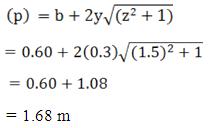
Hydraulic radius (R) 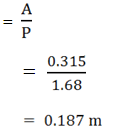
Mean velocity (v) 
Discharge (Q) = A x V
= 0.315 x 0.473
= 0.149
12.4 Energy Depth Relationship
From hydraulic point of view, the total energy of water in any streamline passing through a channel section may be expressed as total head, which is equal to sum of the elevation above a datum, the pressure head, and the velocity head. The total energy at the channel section is given by
![]() (12.6)
(12.6)
where,
H = total energy, z = elevation head above datum, y = depth of water in channel, V = velocity of flow, g = acceleration due to gravity. The specific energy is the total energy at any cross section with respect to channel bed. Considering slope of the channel bed is very small, the specific energy E is
![]() (12.7)
(12.7)
For the channel of rectangular section having width b, the cross sectional area of channel
A = b y
then
![]() (12.8)
(12.8)
Differentiating equation (12.8), equating it to zero for minimum condition, this becomes
![]()
but ![]()
Hence ![]()
When V Vc, Y = (Critical depth)
 (12.9)
![]() is defined as Froude number, for flow to be critical its value is equal to 1. It is greater than 1 for super critical flow and less than 1 for sub critical flow.
is defined as Froude number, for flow to be critical its value is equal to 1. It is greater than 1 for super critical flow and less than 1 for sub critical flow.
Critical depth ( Yc) for rectangular channel is given by
![]() (12.10)
(12.10)
The principle of design of flumes and hydraulic structures (open drop and chute spillways) is based on the concept of specific energy and critical flow.
Example 12.2: Compute the critical depth and specific energy for discharge of 6.0 m3s-1 channel from a rectangular channel. The bottom width of rectangular is 2.4 m.
Solution:
Discharge / unit width (q) = ![]()
Critical depth ![]()
= 0.860 m.
Since specific energy at critical depth (EC) = ![]() yc Therefore EC = 1.290 m.
yc Therefore EC = 1.290 m.
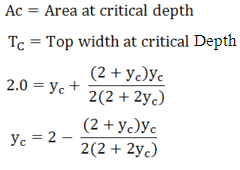
Example 12.3: Determine the critical depth for specific energy head of 2.0 m in a trapezoidal channel of 2.0 m bottom width and side slopes of 1:1.
Solution:
Specific energy at initial depth ( yc) is given by
![]()
As for critical flow 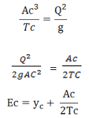
where,
12.5 Velocity Distribution in a Channel Section
The velocity of flow in any channel section is not uniformly distributed. The non- uniform distribution of velocity is due to the presence of a free surface and the frictional resistance along the channel surface. In a straight reach of channel section, maximum velocity usually occurs below the free surface at a depth of 0.05 to 0.15 of the total depth of flow. The velocity distribution in a channel section depends on various factors such as the shape of the section, the roughness of the channel and the presence of bends in the channel alignment. The man velocity of flow in a channel section can be computed from the vertical velocity distribution curve obtained by actual measurements. It is observed that the velocity at 0.6 depth from the free water surface or average of the velocities measured at 0.2 depth and 0.8 depth from free water surface which is very close to the mean velocity of flow in the vertical section. The velocity can be measured by pitot tube or current meter.
References
Schwab, G. O., Fangmeier, D. D., Elliot, W. J., and Frevert, R. K. (1993). Soil and Water Conservation Engineering. John Willey & Sons, Inc., New York, USA: 269.
Subramanya, K. (1992). Flow in Open Channels, Tata McGraw-Hill New Delhi: 34-38.
Suggested Readings
Chow, V. T. (1959). Open-Channel Hydraulics. McGraw-Hill, Inc. Singapore.
Jain C. Subhash. (2001). Open-Channel Flow, John Wiley and Sons, Inc., New York.
James, Larry G. (1988). Principles of Farm Irrigation System Design, John Wiley and Sons, Inc., New York.
Last modified: Saturday, 15 March 2014, 5:51 AM