Site pages
Current course
Participants
General
Module 1:Water Resources Utilization& Irrigati...
Module 2:Measurement of Irrigation Water
Module 3: Irrigation Water Conveyance Systems
Module 4: Land Grading Survey and Design
Module 5: Soil –Water – Atmosphere Plants Intera...
Module 6: Surface Irrigation Methods
Module 7: Pressurized Irrigation
Module 8: Economic Evaluation of Irrigation Projec...
19 April - 25 April
26 April - 2 May
LESSON 15 Underground Pipeline Systems
Water is conveyed from the water source to the cropped field using networks of open channels and or pipe lines. Pipe lines have several advantages over open channels. A properly designed pipeline system saves water, energy consumption and land used for field channels. Underground pipe line types and its components are presented in this lesson.
15.1 Advantages of Underground Pipeline System
The water distribution system of deep wells tube, which are usually owned by the government or cooperative or group farming societies, usually comprise of open channels or buried pipes (underground pipe) with outlets at suitable points in the command area. Buried pipeline water distribution systems, though comparatively more expensive, have major advantages over surface water distribution systems comprising of network of field channels. The following are the major advantages:
-
The farmers get water at or near their fields.
-
Water conveyance losses through seepage, evaporation and breaches in the channels are avoided.
-
The quantity of water delivered from each outlet remains the same, irrespective of the elevation of the outlet.
-
The pipeline can be laid with complete freedom to best suit the requirements of water supply and cost of pipelines, irrespective of the topographic features of the tube well command area.
-
Outlet valves can be provided wherever desired in the pipeline, as determined in the interest of minimising the distance from the outlet to the field, the number of cultivators served by an outlet and ensuring gravity flow from outlet to the fields.
-
Water is supplied to each field plot either directly or through a field channel of short length originating from the outlet.
-
Maintenance cost of the water distribution system is very low.
-
There is full control of the water supply to the fields within a tube well command area.
Limitations
Underground pipe line irrigation system requires high initial investment as compared to open channel systems. This also needs higher operating pressure and additional power to distributed water, whereas in open channel system do not need. The canal carrying svet laden water cannot be connected with underground pipe line system as canal provide very little head and pipe lines are likely to be blocked.
15.2 Low-Head Pipelines
In low head pipe line system water is taken from the water source and directly distributed to basins, borders, and furrows. These low head pipeline works satisfactorily on non-uniform grades, and also at uphill and downhill the land slopes. Such pipeline consists of an inlet, one or more outlets, with head control devices and surge protection structures, air relief valve, flow meter and debris and sand removal devices. Pressure relief, air release, and vacuum relief valves that are used for pressurized pipelines are also used with low-head pipelines. Pipelines permit the conveyance of water on uphill or downhill slopes. These systems are also suitable to undulating topography and can supply water at any part of the farm. The pipe line systems can be buried or on the surface. Surface pipe lines portable and these are brought back after irrigation. The buried pipe lines placed below the ground surface are permanent and called as permanent underground pipeline. Underground pipe line conveyance system is preferred over surface pipe lines as the cultivation can be done on the land above pipeline and it does not affect farming operation.
15.3 Types of Irrigation Water Conveyance Pipeline System
Generally there are three types of irrigation water conveyance pipe line systems. The first is the completely portable surface pipe line system. In this system water is supplied from source and applied to the field from open end of pipe line or using gated outlets. In second system, a combination of buried and surface pipes are used, where buried permanent pipe lines are used to transmit water from source to risers. These risers supply water to surface pipes .In third system, water is delivered from riser/alfalfa valve and channel border or basins, eliminates the need for surface pipes. Water is released on the portion of the field to be irrigated from risers. Irrigation pipe must be sized carefully to deliver enough discharge and at the same time it should be economical.
15.4 Pressure Variations in Irrigation Pipe Lines
Pressure in the pipe line increases or decreases due to change in elevation (uphill or downhill conditions).
The difference in pressure between two locations along a pipeline can be estimated using following equation.
![]() (15.1)
(15.1)
Where,
Hd, Hu pressure at down- and upstream position, respectively (kPa);
HL= energy loss in pipe between the up-and downstream positions (m);
ΔHe = difference in elevation between up-and downstream positions (m);
When the change in elevation between the up-and downstream positions is uphill, the sign of is plus (+) conversely, this sign is negative ( ) when the elevation at the upstream location exceeds the elevation at the downstream location.
Equation 15.2 can be used to estimate the energy loss term,
HL = F · Hf + Ml (15.2)
Where,
F = constant that depends on the number of outlets removing water from the pipe between source and application points
Hf = friction head loss in pipe (m).This is also called as the major loss.
Ml = minor head losses through the fittings provided in the pipeline system (m)
Estimation of Head Loss Due to Friction or Major Loss: Head loss due to friction in irrigation pipe is estimated by using Darcy Weisbach, Hazen Williams or Scobey equations. Fresh live Darcy Weisbach equation computes head loss due to friction in laminar or turbulent flow in pipelines on rational basis as given by equation (15.3).
Darcy Weisbach Equation:
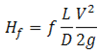 (15.3)
where
Hf = loss of head due to friction
L = length of pipe
D = the inside pipe diameter
V = the mean velocity
g = the acceleration due to gravity, and
f = friction coefficient.
Equation (15.3) is dimensionally consistent and can be used with the same ‘f’ values for FPS or SI units. Values of f have been related to boundary roughness dimensions on pipe surface and determined empirically. These are tabulated in
Hazen Williams Equation: The Hazen Williams equation can be written as:
V = K R0.63 S0.54 (15.4)
where
V = velocity of flow in pipe line
R = the hydraulic radius of pipe and
S = the slope of pipeline (fraction)
In SI units (R in mm),
The constant K = 0.0109K1
Where
K1 = the Hazen – Williams resistance coefficient
The values of K1 range from 144 to 146 for aluminium pipes. K1 values for the pipes of other materials are available in hydraulic handbooks. (James, 1988).
Scobey Equation: The Scobey equation given for riveted steel pipe has also been used to compute head loss in aluminium pipe. The Scobey equation is given by
S = 10-3KV1.9 D-1.1 (15.5)
In SI units velocity (V) in m/s, inside diameter (D) in mm
S = slope (m/m)
The constant K = 516 KS, where KS = Scobey resistance coefficent
The exponents in the Scobey equation may have different values for other pipe materials (Brater and King, 1976). Recommended values for K1 and KS available in the chapter 5 in James (1988), are used to compute pipe size.
Estimation of Minor Losses: Energy losses through fittings and valves also need to be considered in the design of an irrigation pipeline. These so-called ‘‘local’’ or minor losses are frequently estimated by applying a coefficient to the velocity head at the fitting. The sum of all local losses is then added to frictional head loss to estimate total loss in the pipeline. Local loss coefficients to be used in the equation is given:

The values of local loss coefficient (K) due to fittings, joints, valves, elbows and Tees can be obtained from the book entitled “Design and Operation of Farm Irrigation Systems” Kruse, et al. (1980).
15.5 Components of Underground Pipelines
All the low head underground pipe line system requires pump stand as inlet or gravity inlet, gate stands, pressure relief valves, outlets and end plug. Typical components of underground pipeline are illustrated in Fig. 15.1.
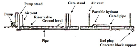
Fig. 15.1. Components of an underground pipeline irrigation system.
(Source: Michael (2010), pp.369)
15.5.1 Inlet Components of Underground Pipeline System
Water inlet components are required to carry water from the source in to low head underground pipelines. An inlet structure is required to develop adequate pressure and full flow capacity so as to distribute water at different points on the farm. Inlet components use a sand trap and trash screen to prevent entry of debris and heavy suspension of sand in the pipe lines.
Pump Stand
A pump stand is located at the inlet end of underground pipeline system. Pump stand must be high enough to provide the pressure needed at all the pipe outlets. Pump stands size is larger than the diameter of pipe line, to dissipate high velocity stream and release of entrapped air before water enters pipeline. A view of the pump stand is shown in Figure 15.2.
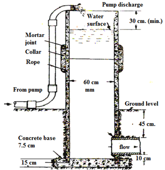
Fig. 15.2. Pump stands for underground pipeline.
(Source: Michael (2010), pp.362)
Gravity Inlets
The gravity inlet is used when water surface elevation of the water source is sufficient to allow gravity flow into the pipeline and to provide the adequate pressure needed at every point of pipe line and outlet. The low head underground pipe line directly connected with water source can be used for delivering water from a minor canal as shown in Fig. 15.3.
Gate Stands
Gate stands are installed to control flow into branch lines. These are installed where branch lines take off from main line. They also prevent high pressure and act as surge chamber. Each outlet of a gate stand is equipped with slide gate or gate valve to release water through a particular gate valve. Fig. 15.4 shows branching off water from main pipeline and (gate stand).
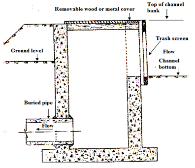
Fig. 15.3. A sectional view of an inlet for taking water from a minor canal into an underground pipeline. (Source: Michael, 2010)
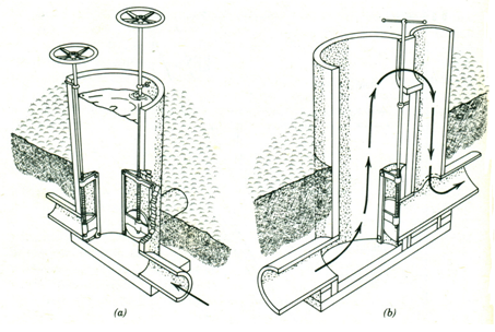
Fig. 15.4. (a) Gate stands and (b) Overflow from Gate stands.
(Source: James, 1988)
Pressure Relief Valves
Pressure relief valves open at certain preset pressure and discharge fluid to relieve the surge. They close immediately when pressure drops below settings. In situation, when rapid changes in flow velocity are necessary, the pressure relief valves are used to prevent water hammering. The air inlet valves (also called vacuum relief) are used at desired places in the pipe lines to prevent vacuum formation. The air vents are also used to release entrapped air and to prevent vacuum formation. These air release devices (air vents) are installed at inlet end near pump stands, sharp bends, high elevation points and before end of pipe lines.
15.5.2 Outlet Structures
Outlet structures are devices that release water from pipelines to any desired locations in the farm. They consist of a riser pipe, and one or more valves to control the flow. The most common outlet consists of a concrete riser pipe and valves to control the flow. The riser valves, hydrants and gated pipes are connected with riser pipe to distribute water to furrow or a border or a basin. A section of riser pipe with alpha-alpha valve is shown through Fig. 15.5.
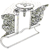
Fig. 15.5. Section of an alfalfa valve for a low head pipeline. (Source: http://www.fao.org/docrep/T0231E/t0231e04.htm)
Hydrants
Hydrants are devices placed over riser valve outlets as a means of connecting portable gated pipes to the pipeline. They are portable so that they can be moved from one valve outlet to another to serve the portion of the field which is being irrigated at a particular time. Hydrant can also be used for connecting the suction hose of a pump to the water supply carried in the pipeline under low pressure, so that the pump can develop the high pressure.
End Plug
The function of an end plug is to close a line and to absorb the pressure developed at the end of the line, on account of water hammer. The plug is backed by a masonry block which provides sufficient strength to meet unexpected high pressure developed due to sudden opening or closing of valves.
15.6 Underground Pipeline Materials
Both reinforced concrete pipes and PVC pipes are used for constructing water distribution systems in the command areas of wells. PVC pipes are often preferred because of the ease of installation and ensure leak proof joints. Other factors favouring its use are speed of laying and greater resistance to internal friction, as compared to concrete pipes of a given diameter, to convey large quantities of water. However, skill and adherence to proper procedure in laying the pipes and accessories can be used more economically and with equal efficiency, as compared to PVC pipes on plain land. PVC pipes have distinct advantages over concrete pipes. In undulation topography, however, they need to be buried to avoid UV degradation. HDPE pipe can be used above ground level.
References
Brater, E.F., and King, H.W. (1976). Handbook of Hydraulics, 6th ed., McGraw-Hill, New York, USA.
http://www.fao.org/docrep/T0231E/t0231e04.htm
James, Larry G. (1988). Principles of Farm Irrigation System Design, John Wiley and Sons, Inc., New York.
Kruse, E. G., Humpherys, A. S., and Pope, E. J. (1980). Farm Water Distribution Systems. (In Design and Operation of Farm Irrigation Systems, Edited by Jensen, M.E). An ASAE Monograph Number 3, American Society of Agricultural Engineers, Michigan USA: 395-446.
Michael, A. M. (2010). Irrigation Theory and Practice, Vikas Publishing House PVT Ltd, Noida, India: 362- 369.
Suggested Readings
Schwab, G. O., Fangmeier, D. D., Elliot, W. J., and Frevert, R. K. (1993). Soil and Water Conservation Engineering. John Willey & Sons, Inc., New York, USA: 408.
Last modified: Thursday, 6 March 2014, 6:00 AM