Site pages
Current course
Participants
General
Module 1:Water Resources Utilization& Irrigati...
Module 2:Measurement of Irrigation Water
Module 3: Irrigation Water Conveyance Systems
Module 4: Land Grading Survey and Design
Module 5: Soil –Water – Atmosphere Plants Intera...
Module 6: Surface Irrigation Methods
Module 7: Pressurized Irrigation
Module 8: Economic Evaluation of Irrigation Projec...
19 April - 25 April
26 April - 2 May
LESSON 16. Design and Operation of Underground Pipeline System
16.1 Design of Underground Pipeline Systems
The design of underground pipe line system requires information on land topography, location of water source and water discharge. Pump stands must be of high elevation to allow sufficient operating head for the pipeline. However, stands higher than necessary may permits high heads of water to build up, leading to excessive line pressures. The working pressures in the pipeline are kept within one-fourth the internal bursting pressures of the pipe. When it is necessary to design pipelines with higher heads, reinforced concrete pressure pipes are used. The sizes of the outlets are selected to suit the flow required at diversion points. The PVC and HDPE are also used for water distribution at low and moderate pressure. The components of the systems such as pipeline size and height of Pump stands and control stands must be designed so as to obtain a balanced water distribution and provide trouble free operation.
The height of water in the pump stands is estimated as follows:
Depth of water in pump stand (HPS ) (m) = Reduced level at height point (m) + losses in the pipe line Reduced level at pump stand (m). A free board of 0.5m of water head is added to get the height pump stand.
Losses in pipe line are head loss due to friction and also known as major loss. Various equations such as Darcy-Weisbach, Hazen Williams and Scobey have been proposed to determine head loss due to friction (Refer lesson 15). The Darcy’s Weisbach equation is scientifically based and applicable to both laminar and turbulent flows.
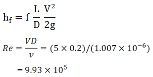
The Darcy-Weisbach equation is
![]() (16.1)
(16.1)
where,
Hf = head loss due to friction,(m)
f = friction factor,
L = length of the pipe(m)
d = Inside diameter of the pipe (m)
V = mean velocity of flow (m s-1)
g = acceleration due to gravity (m s-2)
The friction factor f is function of Reynolds number (Re) and relative roughness &. For laminar flow (Re , the friction factor is
 (16.2)
where
![]()
V = velocity, m s-1
D = diameter of pipe, m
ν = Kinematic viscosity, m2 s-1
For Re between 2000 and 100,000 (Turbulent flow)
f = 0.32 Re -0.25 (16.3)
For Re > 100,000 (Fully turbulent flow)
![]() (16.4)
(16.4)
For most commercial materials, the friction factor is represented by the semi- empirical equation
![]() (16.5)
(16.5)
Minor Losses
Head losses in underground pipeline are also caused by inlets, bends, gate valves, outlets (rivers, valves etc.) and other appliances such as fittings expansions and constructions due to entry and exit losses and abrupt and gradual changes in velocity. These losses are, referred to as minor losses.
These losses are given by equation (16.6).Each term in the equation represents the head loss due exit, entry or fitting or connections in the pipeline.
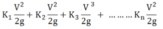 (16.6)
Where,
K1, K2, ... Kn are coefficients for each item where minor head loss exists.
These minor loss coefficients can be obtained from Michael, (2010).
The values of coefficient as 0.5 for pipe flush with wall, 0.1 for bell entrance and 1.0 for bends. are used. If the gated pipes are used, then pressure required to operate these pipes are included (Michael, 2010).
Diameter of Pipe Line
The diameter of pipe line is computed considering the head loss due to friction in pipe line (Equation 16.1) and discharge. Too small, diameter will increase the pumping cost due to increased frictional head losses and too large pipe diameter will add to the system cost. The material and size of pipe are selected considering the hydraulically efficiently and pumping cost.
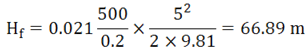
Example 16.1: A 500 m long 200 mm diameter pipe is used as underground irrigation water supply system. The velocity of water flow is 5m/s, the PVC pipe is used which has =0.00026 m. Use kinematic viscosity v as = 1.007 , Determine the head loss in pipe.
Solution:
The head loss due to friction is computed using the Darcy-Weisbach equation
The relative roughness
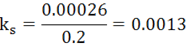
From Moody diagram, the friction factor (f) (at = 9.93 X 10⁵ and ![]() = 0.0013) = 0.021
= 0.0013) = 0.021
Head loss due to friction (Hf)
16.2 Laying Out of Underground Pipeline System
Preparation of contour map is essential requirement to lay and construct underground pipeline for a command area. The map should depict North direction and important features locating revenue division and sub divisions. The map should show field boundaries, streams, rivers, tanks, earth embankments, roads, wells and village boundary and other major features of the area which will come under the command of the tubewell and the area immediately adjoining it. The alignment of the buried pipeline water distribution system and the location of the valves should be planned based on the inspection of the field contours and the various features on the ground. The alignment of the earthen field channels and essential field structures like inverted siphons are decided based on the ground elevation. Profiles along each pipe and channel route are surveyed and plans are prepared showing depth, gradient and earth work along their length and the location of the structures. These include inlet, water control and diversion structures, air release vents and end plugs.
After laying of PVC pipes and backfilling of the trenches and construction of the outlet structure, the water is allowed to pass through the pipeline. All air in the pipe should be allowed to escape through the pressure release pipe. For 3 to 4 days, all the outlets are kept open for 3 to 4 hours, with the pump in operation, in order to check if there are any leakages in the pipe or in any of the outlets. If leakage is noticed, repairs are done after draining the entire pipeline system.
16.3 Operation and Maintenance of Underground Pipeline Systems
The underground pipeline may fail due to i) lack of inspection or maintenance, ii) improper construction, iii) improper design and iv) wrong manufacturing processes and poor quality materials used.
The underground pipelines operate without trouble when it is properly designed and correctly installed. Inadequate procedures in design and installation and unforeseen situations give rise to the following troubles.
a) Development of longitudinal cracks in the pipe, usually at the top or both at top and bottom
b) Telescoping of sections
c) Pushing of the pipe into the stands
d) Development of circumferential cracks
e) Surging or intermittent flow of water
Leak Testing and Repair
All buried low pressure irrigation pipelines should be tested for leaks before the trench is filled. The pipeline should be filled with water and slowly brought up to operating pressure with all turnouts closed. Any length of pipe section or joints showing leakage should be replaced and the line retested. The water should remain in pipelines throughout the backfilling of trenches, because the internal pressure helps to prevent pipe deformation from soil loading and equipment crossings. Underground pipelines should be inspected for leakage at least once a year. Leaks may be spotted from wet soil areas above the line that are otherwise unexplained. Small leaks in concrete pipeline can be repaired by carefully cleaning the pipe exterior surrounding the leak, then applying a patch of cement mortar grout. For larger leaks, one or more pipe sections may have to be replaced. Longevity of concrete pipelines can be increased by capping all opening during cold winter months to prevent air circulation. Small leaks in plastic pipe, except at the joints, can sometimes be repaired by pressing a gasket-like material tightly against the pipe wall around the leak and clamping it with a saddle. Where water is supplied from a canal to portable surface pipe, sediment often accumulates in the pipe. This sediment should be flushed out before the pipe is moved. Otherwise, the pipe will be too heavy to be moved by hand and may be damaged if it is moved mechanically. Buried plastic pipelines can be expected to have a usable life of about 15 years, if well maintained. The annual cost of maintenance can be estimated as approximately 1% of the installation cost.
References
Nikuradse, J. (1932). Laws of Turbulent Flow in Smooth Pipes, NASA.
James, Larry G. (1988). Principles of Farm Irrigation System Design, John Wiley and Sons, Inc., New York: 326.
Michael, A. M. (2010). Irrigation Theory and Practice, Vikas Publishing House PVT Ltd, Noida, India: 371-374.
Suggested Readings
Kruse, E. G., Humpherys, A. S., and Pope, E. J. (1980). Farm Water Distribution Systems, (In Design and Operation of Farm Irrigation Systems, Edited by Jensen, M.E). An ASAE Monograph Number 3, American Society of Agricultural Engineers, Michigan USA: 395-446.
Last modified: Thursday, 6 March 2014, 6:17 AM