Site pages
Current course
Participants
General
Module 1: Fundamentals of Reservoir and Farm Ponds
Module 2: Basic Design Aspect of Reservoir and Far...
Module 3: Seepage and Stability Analysis of Reserv...
Module 4: Construction of Reservoir and Farm Ponds
Module 5: Economic Analysis of Farm Pond and Reser...
Module 6: Miscellaneous Aspects on Reservoir and F...
5 April - 11 April
12 April - 18 April
19 April - 25 April
26 April - 2 May
Lesson 13 Determination of Location of Seepage Line
13.1 Phreatic Line in Earth Dam
Phreatic line is also known as seepage line or saturation line. It is defined as an imaginary line within a dam section, below which there is a positive hydrostatic pressure and above it there is a negative hydrostatic pressure. The hydrostatic pressure represents atmospheric pressure which is equal to zero on the face of phreatic line. Above the phreatic line, there is capillary zone, also called as capillary fringe, in which the hydrostatic pressure is negative. The flow of seepage water, below the phreatic line, reduces the effective weight of the soil; as a result shear strength of a soil is reduced due to increased intergranular pressure in earth fill material.
13.2 Derivation of Phreatic Line with Filter
In this case, before going directly for derivation, the important features of phreatic line must be known. From the experimental evidence, it has been found that, the seepage line is pushed down by the toe filter and is very close to parabolic shape except at the junction point of the upstream face. The upstream face of the dam represents 100% equipotential line when it is covered by the water; under this condition the seepage line should be drawn perpendicular to this face at the junction point.
Casagrande method is used for deriving the phreatic line (Fig. 13.1); the procedure is described as follows:

Fig. 13.1. Derivation of phreatic line in earth dam. (Source: Suresh, 2002)
a) Let the phreatic line is assumed to be a base parabola with its focus at point F, i.e. at the starting point of the filter, FE.
b) AB is the upstream face of the earth dam and L is the horizontal projection of face AB on the water surface. Measure the distance BC equal to 0.3L. Count point C as a starting point of base of parabola.
c) For deciding the position of directrix of the parabola, the principle which states that every point of the parabola is at equidistance from the focus as well as directrix. Hence, considering C as a center and CF as radius, an arc is drawn which cut the horizontal line CB at point O. Since CO = CF, hence vertical line OH will be directrix of parabola.
d) The last point G of the parabola will fall at the middle of the points F and H.
e) The intermediate points of parabola are located on the principle that their distance from the focus and directrix are the same. Here to locate the point P as an intermediate point, a vertical line DP is drawn at any distance x from the F. Now considering the distance DH as radius with F as a center, an arc is drawn which cuts the vertical DP at point P.
f) Now all there obtained points are joined by free hand to get the base parabola. However, this needs to be corrected at the entry point, for the feature that phreatic line must be started from the point B only, not from C. It should be sketched perpendicular to the upstream face AB, as it is 100 percent equipotential line. Now phreatic line is sketched by free hand in such way that, it should be perpendicular to face AB and meets to rest of the points of the parabola tangentially. In addition, the base parabola should also be met perpendicular, to the downstream face of the dam at point G.
13.3 Equation of Parabola
The equation of base parabola can be derived from its basic properties i.e. the distance of any point P(x, y) on the parabola from its focus is the same as the distance of the point P(x, y) from directrix.
Thus we have,
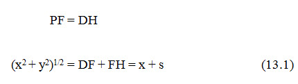
Where, s = focal distance (FH)
From equation 13.1,
This is the desired equation of base parabola.
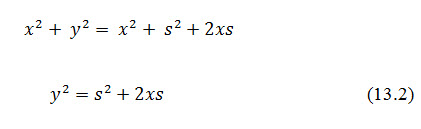
For deriving the expression of discharge (q) for the earth dam equipped with horizontal filter, the Darcy's law is used. According to which, the discharge (q) through vertical section PD, is equal to:
Partial differentiation of Eqn.13.2, resulted
Substituting the value of in Eqn. 13.3, the rate of seepage flow through the dam is given by:
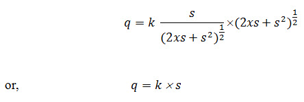
This is the expression for computing the rate of seepage discharge through the body of earthen dam, in terms of focal distance s. The distance s can be determined either graphically or analytically. Considering C as co-ordinate, the value of s can be obtained as:
From Eqn: 13.1
![]()
At point C, x = D and y = H
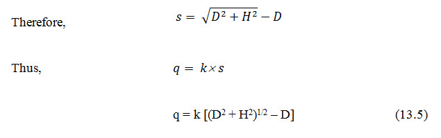
By using this equation, if the value of coefficient of permeability (k) and focal distance (s) are known, the discharge (q) can be calculated. This gives an accurate value of seepage rate and is applicable to such dams, which are provided with horizontal drainage (filter) system but can also be used for other types of dam section.
13.4 Phreatic Line in Earthen Dam without Filter
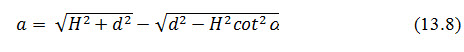
The position of phreatic line in an earth dam without filter can be determined using the same manner, as in previous case i.e. with a filter. In this case, the focal point (F) of the parabola will be the lowest point of the downstream slope (Fig. 13.2). The base of the parabola BJC cut at a point J on downstream slope and is extended beyond the limit of the dam, as indicated by dotted line, but the seepage line should be emerged at point K, tangential to downstream face. In this way, the phreatic line should be shifted to the point K from J. The distance KF is known as discharge face, which always remains under saturation condition. The correction JK (say) by which the base of parabola need to be shifted downward, can be determined by graphical and analytical methods.
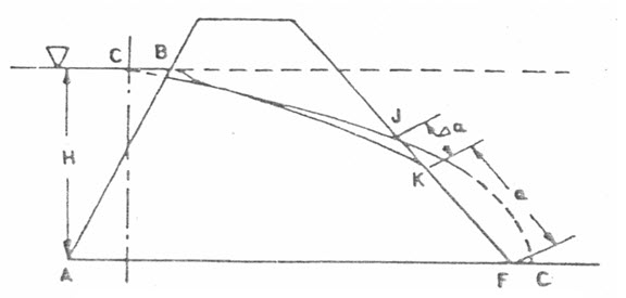
Fig. 13.2. Phreatic line without filter.
(Source: Suresh, 2002)
1. Graphical Method
Casagrande has given a general solution to determine the value of for various degrees of inclination of the discharge face. The inclination angle may be more than 90o, especially in case of rock fill dam.
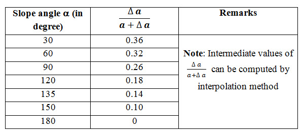
Let, if a is the slope angle of the discharge face with the horizontal is known, and then various values of ![]() corresponding to a are given by Casagrande (Table 13.1).
corresponding to a are given by Casagrande (Table 13.1).
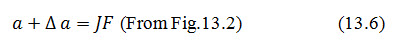
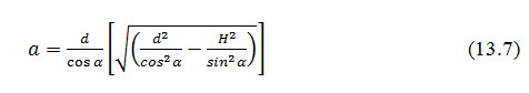
Here, JF indicates the distance of the focus from the point, where base of parabola cuts downstream face. The values of and can be obtained by Eqn (13.7) and Table 13.1.
Table 13.1. Values of ![]() for various slope angles (a)
for various slope angles (a)
2. Analytical Method
Under this method the following cases are considered, for determining the position of discharge face (a) at the downstream face of the dam.
Case (1) when slope angle a < 30o
Schaffernak and van Iterson (1916) have derived an equation for finding the value of to fix the position of K. The equation is given as
Where, d = horizontal distance from the origin point of the phreatic line to the toe of downstream face of the dam, and h = depth of the water towards the upstream face of the dam (Fig. 13.3).
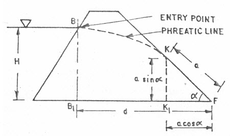
Fig. 13.3. Phreatic line without filter. (Source: Suresh, 2002)
The above equation was derived on the assumption that, the hydraulic gradient is equal to the slope of the phreatic line, which is valid for relatively flat downstream slope.
Case (2) when slope angle lies between 30o to 60o
Casagrande has also derived the following equation for calculating the value of as:
This equation gives satisfactory result for values of a ranging from 30 to 60o, but for steeper slopes than 60o, this yields a quite higher value. For such case, Casagrande has suggested for modification in above equation, to use sin a in place of tan a. In other words, it can be said that the hydraulic gradient (i) is equal to but not as as taken in the previous case. Here, s is the distance measured along the curve.
Therefore according to Darcy's law,
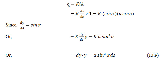
Integrating the eq. (13.9) with the limit as:
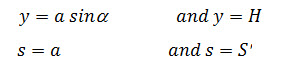
Where, is the total length of parabola from the point B to F.
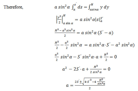
Ignoring -ve sign we get,
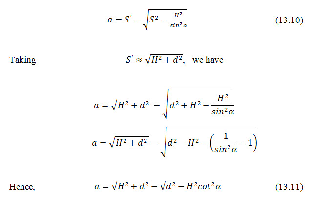
This is the required equation for computing the value of when slope angle a exceeds 60o.
Keywords: Seepage line, Phreatic line, Slope angle, Filter, Parabola
References
Garg, S. K. (2011). Irrigation Engineering and Hydraulic Structures. Twenty fourth Revised Edition.
Suresh, R. (2002). Soil and Water Conservation Engineering. Standard Publishers.
Suggested Readings
Central Water and Power Commission (1960). Embankment, Manual. Ministry of Irrigation and Drainage Power, New Delhi.
Creager, W. P. and Julian Hinds (1968). Engineering for Dams. Vol. I, II and III. Wiley Eastern, New Delhi.
Murthy, V. V. N. and Jha, M. K. (2011). Land and Water Management Engineering. Kalyani Publishers.
Last modified: Monday, 3 February 2014, 10:36 AM