Site pages
Current course
Participants
General
Module 1: Fundamentals of Reservoir and Farm Ponds
Module 2: Basic Design Aspect of Reservoir and Far...
Module 3: Seepage and Stability Analysis of Reserv...
Module 4: Construction of Reservoir and Farm Ponds
Module 5: Economic Analysis of Farm Pond and Reser...
Module 6: Miscellaneous Aspects on Reservoir and F...
5 April - 11 April
12 April - 18 April
19 April - 25 April
26 April - 2 May
Lesson 20 Stability Analysis I
20.1 Introduction
Failure against dam stability occurs whenever the shearing force along any surface through the embankment and its foundation exceeds the shearing resistance along that surface. The trace of the surface of sliding on a cross-sectional view generally may be approximated by either a straight line, the arc of a circle, a portion of a logarithmic spiral, or a composite of such lines. The stability analysis is made by considering various possible surfaces of sliding and computing the factor of safety against stability failure for each. The factors of safety are defined as the available shearing resistance divided by the shearing force. The sliding surface with the lowest factor of safety is the critical one.
This is a limit equilibrium type of approach.
The various cases of loading for which embankment slopes are analyzed together with the minimum factors of safety recommended for these cases are tabulated below:
Table 20.1. Factor of safety for various conditions (Source: Davis, 1969)
|
Condition |
Minimum Factor of Safety |
|
End of construction case, both upstream and downstream slopes |
1.25 |
|
With earthquake loading in addition |
1.0 |
|
Steady seepage at partial pool upstream slope |
1.5 |
|
With earthquake loading in addition |
1.25 |
|
Steady seepage downstream slope |
1.5 |
|
With earthquake loading in addition |
1.25 |
|
Rapid drawdown upstream slope |
1.25 |
|
With earthquake loading in addition |
1.0 |
The shearing strengths of the embankment and foundation materials are different for each of the cases mentioned above. The differences are due primarily to differences in the conditions of consolidation and drainage which obtain in each of the cases. Four ways of expressing the shear strength are in general use.
In terms of total applied stresses at time of failure
In terms of effective stresses at time of failure
In terms of consolidation stresses at time of consolidation, for a condition prior to applying the increment of load, which causes failure.
As in situ shear strength (generally used for foundation)
For each condition of consolidation and condition of drainage during shear the shear strength may be expressed in terms of the parameters c and f according to the following expression:
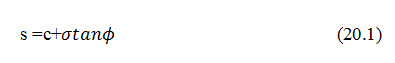
Where, s = shear strength of soil, c = cohesion, s = normal stress, and = angle of internal friction.
Either total stresses, effective stresses or consolidation stresses may be used for the normal stress. The values of c and will be different for each condition of shearing and for each normal stress used. The liner relationship indicated by the expression is only an approximation of actual shear strength and applies only to a limit range of normal stresses.
Several methods are available for making stability analysis including the circle method, the log-spiral methods, the slices method, and the sliding block method. When carried out using consistent assumptions and when the sliding surfaces approximate each other reasonably well all four methods gives substantially the same results.
Another approach to the stability problem is to determine the ratio of shear resistance to shear stresses at points throughout the embankment and its foundation. The location of any overstressed zones as well as the average of the ratios of shear resistances to shear stresses along some potential surface of sliding is of interest. The finite element method of analysis using an electronic computer is a powerful tool in this connection. Use of this approach should be checked using one of the limit equilibrium stability methods mentioned above.
Simplified methods of stability analysis such as the infinite slope analysis can be made for cohesion-less materials, which are relatively incompressible since pore pressures that develop in them because of shear stresses are small and can be neglected. The slices method of stability analysis is applicable to all types of soils and conditions of loadings. This method is described in lesson 21.
20.2 Infinite Slope Analysis
The infinite slope analysis is made by considering a typical vertical slice of a long shallow sliding mass (Fig. 20.1). The length of the sliding mass is so great compared with the depth that end effects on the sliding mass are negligible. The infinite slope type of analysis is useful in connection with analyzing the stability of the faces of embankments/dams where the shell is composed of cohesion-less material. Analysis may be made where seepage is unidirectional; the factor of safety of the slope is as follows:
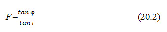
Where, i = face angle of the slope
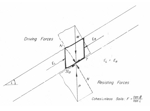
Fig. 20.1. Infinite slope.
(Source: Davis, 1969)
The required angle of friction for a factor of safety of 1.0 is called the developed angle of friction. In the above case equal i.
When seepage occurs additional frictional resistances is required for stability. For the case of seepage parallel to the face of the slope and in the downward direction the factor of safety may be expressed as follows
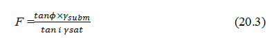
Where, gsubm= unit weight of material, submerged, and = unit weight of material, saturated= +
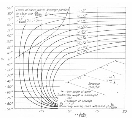
Fig. 20.2. Stability chart for infinite slope of cohesionless material.
(Source: Davis, 1969)
The increase w in developed friction angle, which is required in case of seepage in various directions and at various gradients, is given in the chart (Fig. 20.2). For the use of the chart, the gradient j needs to be known. This may be determined from a flow net or in certain simple cases as indicated below, may be estimated. When the seepage line is parallel to the face of an embankment, the gradient is equal to the sin of the slope angle i. For the case of complete drawdown for an embankment on an impervious foundation, seepage occurs horizontally out of the lower portion of the upstream slope (Fig 20.3a). The gradient for seepage in this case is equal to about tan i. If drawdown is not complete, the flow net is obtained (Fig 20.3b). In this case seepage just below the water level of the reservoir is perpendicular to the face of the dam and at a gradient about equal to sin i.
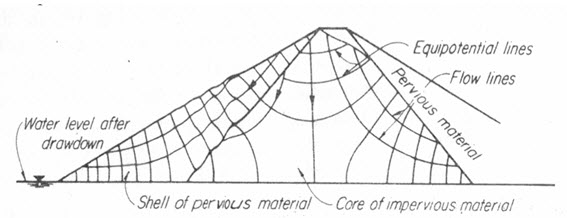
(a) Total drawdown
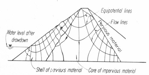
(b) partial drawdown
Fig. 20.3. Flow net in a dam with core of impervious material.
(Source: Davis, 1969)
When the gradient has been determined or estimated, the term j (/) as defined on the chart (Fig. 20.2) can be computed and with this value the chart can be entered. The required friction angle is obtained by adding the slope angle and the angle ω obtained from the chart. The letter value is read from the chart utilizing the family of curve which represents the anglew.
Fig. 20.2 indicates the locus of points representing cases where seepage is parallel to the slope and in a downward direction and (/) equals 1. These are the cases that correspond to Eqn. (20.3) for seepage parallel to the face of the slope.
Assuming that the gradient is equal to sin i, the most critical direction for seepage is upward at an angle α about equal to the angle of the slope i. For embankment with slopes flatter than about 15o, however, the factor of safety for a gradient equal to sin i is about the same whether seepage is downward parallel to the slope, horizontal or upward perpendicular to the slope. Vertical seepage whether upward or downward has no effect on the. Of course, if the upward seepage force equals the submerged weight of the soil, a quick condition develops. Also any upward seepage reduces the resistance of the element considered to driving forces other than the driving forces created by weight of the element itself as the force created by seismic acceleration.
20.3 Location of Critical Circles
Circular surfaces of sliding may be either toe circles, slope circles, or midpoint circles (Fig 20.5). In homogeneous material, toe circles are the critical circles for steep slopes. For flat slopes, midpoint circles are critical, but these may be restricted by the presence of strong stratum at shallow depth. The critical circle breaks out on the face of the slope (Fig. 20.5 d).
All the circles illustrated above are for the case where the crest of the dam is of limited width. The critical circle usually breaks out close to edge of the crest on the opposite side from the face being analyzed for stability. In non-homogenous material, the critical circle is located so that a maximum portion of its length passes through the lowest shear strength material. The lowest shear strength material may
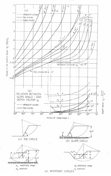
Fig. 20.5. Stability Chart. (Source: Davis, 1969)
be the core of the dam or the foundation layer. To facilitate circular arc stability analyses where the face of the core is the lowest shear strength material, it is permissible to assume a virtual cross section of the dam where upstream face of the core has curved shape matching the circular arc surface under investigation.
Keywords: Shearing force, Shearing resistance, Stability failure, Factors of Safety, Sliding surface
References
Davis, C.K. (1969). Handbook of Applied Hydraulics. Second Edition. McGraw-Hill, New York.
Suggested Readings
Anonymous. (1936) Calculations of the Stability of Earth Dams, Trans. 2nd Congress on Large Dams. Washington D.C.
Janbu, N. (1954) Stability Analysis of Slopes with Dimensionless Parameters. Harvard Soil Mechanics Series.
Last modified: Tuesday, 4 February 2014, 6:30 AM