Site pages
Current course
Participants
General
Module 1: Introduction and Concept of Soil Erosion
Module 2: Water Erosion and Control
Module 3: Wind Erosion, Estimation and Control
Module 4: Soil Loss- Sediment Yield Estimation
Module 5: Sedimentation
Module 6: Topographic Survey and Contour Maps
Module 7: Land Use Capability Classification
Module 8: Grassed Waterways
Module 9: Water Harvesting
Module 10: Water Quality and Pollution
Lesson 6 Bunding Methods for Water Erosion Control
Bunding is a mechanical method for control of soil erosion. When agronomical measures alone are not sufficient, such and other mechanical measures should be adopted.
6.1 Mechanical Measures for Water Erosion Control
Mechanical practices are engineering measures used to control erosion from slopping land surfaces and thus land surface modification is done for retention and safe disposal of runoff water. In the design of such practices, the basic approach is (i) to increase the time of stay of runoff water in order to increase the infiltration time for water, (ii) to decrease the effect of land slope on runoff velocity by intercepting the slope at several points so that the velocity is less than the critical velocity, and (iii) to protect the soil from erosion caused by the runoff water. The mechanical measures adopted for soil and water conservation are: bunding, terracing etc.
6.2 Bunds (Contour Bunds, Graded Bunds) and their Design
Bund is an engineering measure of soil conservation, used for creating obstruction across the path of surface runoff to reduce the velocity of flowing water. It retains the running off water in the watershed and thus to helps to control soil erosion. Bunds are simply embankment like structures, constructed across the land slope. Different types of bunds are used for erosion control and moisture conservation in the watersheds. When the bunds are constructed along the contours with some minor deviation to adapt to practical situation, they are known as contour bunds. If the bunds are constructed with some slope, they are known as graded bunds. No farming is done on bunds expects at some places, where some types of stabilization grasses are planted to protect the bund. The choice of the types of bund is dependent on land slope, rainfall, soil type and the purpose of the bund in the area. The contour bunds are recommended for areas with low annual rainfall (< 600 mm) agricultural fields with permeable soils and having a land slope of less than 6%, while graded bunds are used for safe disposal of excess runoff in areas with high rainfall and relatively impervious soil.
In India, contour and graded bunding have been practiced for a long time and the Indian farmers have very good knowledge about it. From the experience, it has been found that bunds could stand well in shallow, medium and medium deep soils. In deep black soil, due to cracks in dry condition, the bunds fail. Through these cracks, water continues to flow and big breaches are usually created. This results in severe damage to the fields. Although various erosion problems exist in black cotton soils, contour bunding cannot be taken up in such soils successfully.
6.2.1 Contour Bunds
Contour bunds are laid out in those areas which have less rainfall and permeable soils. The major requirements in such areas are prevention of soil erosion and conservation of rain water in the soil for crop use. To maximize the conservation of rainwater in the soil, no longitudinal slope is provided to the field strip. In such a system of bunding, the bunds are designed to be laid out on contours with minor adjustments, wherever necessary.
The main functions of contour bunds are:
It reduces the length of slope which in turn reduces the soil erosion.
The water is impounded for some time and gets recharged into the soil which helps in crop cultivation.
The limitations of contour bunds are:
The contour bunds are suitable for those areas, which receive the annual rainfall less than 600 mm
It is not suitable for clayey soils
Contour bunding is not suitable on the land slopes greater than 6%.
6.2.2 Graded Bunds
Graded bunds are laid out in areas where the land is susceptible to water erosion, the soil is less permeable and the area has water logging problems. A graded bund system is designed to dispose of excess runoff safely form agricultural fields. A graded bund is laid out with a longitudinal slope gradient leading to outlet. The gradient can be either uniform or variable. The uniformly-graded bunds are suitable for areas where the bunds need shorter lengths and the runoff is low. The variable-graded bunds are required where bunds need longer lengths, owing to which the cumulative runoff increases towards the outlets. In these types of bunds, variations in the grade are provided at different sections of the bund to keep the runoff velocity within the desired limits so as not to cause any soil erosion.
The limitations of the system are:
Due to crossing of farm implements, the bunds are disturbed and some soil is lost.
Proper maintenance is required at regular interval.
6.3 Design Specification of Bunds
The following parameters should be considered for bund design:
1. Type of Bund: The type of bund (contour or graded bund) to be constructed depends upon the rainfall and soil condition. Contour bunds are preferred for construction in areas receiving annual rainfall less than 600 mm and where soil moisture is a limiting factor for crop production. Graded bunds are recommended in heavy and medium rainfall areas. The grade to be provided to the bund may vary from 0.2% to 0.3%.
2. Spacing of the Bunds: The basic principles to be adopted for deciding the spacing of bunds are: (1) the seepage zone below the upper bund should meet the saturation zone of the lower bund; (2) the bunds should check the water at a point where the water attains erosive velocity and (3) the bund should not cause inconvenience to the agricultural operations.
For determining the spacing of the bunds the following formula is used:
 (6.1)
(6.1)
where,
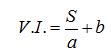
V.I. = vertical interval between consecutive bunds,
S = land slope (percent) and
a and b = constants, depend upon the soil and rainfall characteristics of the area.
The above equation is area specific. It can be modified for areas with different rainfall amounts.
1. For the areas of heavy rainfall:
![]() (6.2)
(6.2)
2. For the areas having low rainfall
![]() (6.3)
(6.3)
In which, VI is in cm and S is in percent.
The bund spacing can not be easily located on the ground on the basis of vertical interval. But the horizontal interval (spacing) can be easily measured on the land surface. For this purpose, the relationship between horizontal and vertical spacing is important and is given below.
H.I. = V.I. / S
Here, H.I. indicates the horizontal distance of the bund and V.I. is the vertical interval.
3. Size of the Bund: The size of bund includes its height, top width, side slopes and bottom width. The height of bunds mainly depends upon the slope of the land, spacing of the bunds and the maximum intensity of rainfall expected in the area. Once the height of the bund is determined, other dimensions of the bund viz., base width, top width and side slopes are determined using the information on the nature of the soil. Depending on the amount of water to be intercepted, the height of the bund can be calculated as given below (Fig. 6.1).
Let X = height of the bund, L = distance between bunds, V = vertical interval between bunds, and W = width of water spread.
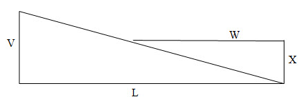
Fig. 6.1. Basic diagram for deriving the height of bund.
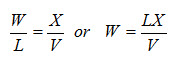 (6.4)
(6.4)
Considering 1m length of the bund, amount of water stored = ½ WX
Substituting for W from Eqn. 6.4, amount of water stored
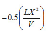 (6.5)
(6.5)
Assuming that any time the maximum rainfall, which the bunds have to withstand, is 15 cm high; water retained by 1 m length of the bund
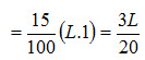 (6.6)
(6.6)
Now equating both these values:
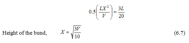
When, the land slope is expressed as S per cent.
V = LS/100
 (6.8)
(6.8)
L and X are in meters and S is the per cent slope. This is the theoretical height and suitable free board is added to arrive at the practical height of the bund.
Base width of the bund depends upon the hydraulic gradient of water in the soil. Side slopes are dependent upon the angle of repose of the soil. A general value of the hydraulic gradient assumed is 1:4. Side slopes of the bund recommended for different soils are given in Table 6.1.
Table 6.1. Side slopes of the bunds recommended for different soil types (Source: Murthy, 1994)
|
Side slopes |
1.5 to 1 |
2 to 1 |
2.5 to 1 |
|
Soil types |
Red Gravel |
Light Sandy loam |
Sand |
|
Light red loam |
Clay |
||
|
Black loam |
Black cotton soil |
||
|
White gravel |
Soft decomposed rock |
Some of the typical cross sections of bunds are shown in Table 6.2. Usually a higher size of the bunds than required by the hydraulic considerations is adopted to allow for the settlement and poor maintenance by the cultivators.
Table 6.2. Typical bund cross-sections for scarcity areas
(Source: Murthy, 1994)
|
Soil Types |
Top width (m) |
Bottom width (m) |
Height(m) |
Side Slope |
|
Full maximum or soil layer up to 7.5 cm |
0.45 |
1.95 |
0.75 |
1:1 |
|
Soil layer from 7.5 cm to 23 cm |
0.45 |
2.55 |
0.83 |
1.25 :1 |
|
Full soil or soil layer from 23 cm to 45 cm |
0.53 |
3.0 |
0.83 |
1.50: 1 |
|
Full soil 45 cm to 80 cm |
0.60 |
4.2 |
0.90 |
2:1 |
4. Length of Bund. The length of bund is determined by calculating the horizontal interval of the bund formed. The length of bund per hectare area of land is given as:
L= 10000/H.I
= (10000*S)/(VI*100)
= 100(S/VI) (6.9)
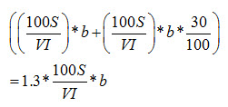
5. Earth Work: The earth work of bunding system includes the sum of earthwork made in main bunds, side bunds and lateral bunds formed in the field. The earthwork of any bund is obtained by multiplying the cross-sectional area to its total length. The total earthwork can be given by the following equation.
Et = Em + Es + El (6.10)
where, Et = total earthwork, Em = earthwork of main bunds, Es = earthwork of side bunds, El = earthwork of lateral bunds, Em = cross-sectional area * total length of bund = (100S/VI)* cross-sectional area.
Therefore, Es + El = ((100S/VI) * 30/100) * cross-sectional area
Therefore, total Et = Em + Es + Et
= (100S/VI + 30S/VI)* cross-sectional area
= 130S/VI * cross-sectional area
Et = 1.3 * (100S/VI) * cross-sectional area of bund
In the above calculation the value of Es + El is taken as 30% earth work of main contour bund (Em) by assuming that the length of side and lateral bund to be as 30% of the length of main bund and their cross-sectional area is also equal to main bund.
6. Area Lost due to Bunding: It is calculated by multiplying the length of contour bund per hectare with its base width. i.e
AL = 10000/HI * b
= 100S/VI * b
Where, b is the base width of bund.
This equation computes only the area lost due to main contour bund and not the area lost due to side and lateral bunds. Usually, the area lost due to side and lateral bunds is taken as 30% of the area lost due to main contour bund. Thus, the total area lost due to contour bunding is:
The above equation can also be written in the following form to compute the area lost in percentage due to bunding:
AL (%) = 1.3*S*b/VI
6.4 Construction of Bunds
Construction of bunds should start from the ridge and continue down the valley. This will ensure protection of the bunds if rains occur during construction. The base width area of the bund should be cleared of vegetation and the soil in this area should also be slightly distributed so that good binding can be achieved when the bund is formed over it. The burrow pits for the soil are generally located on the upstream side of the bund. It should have a uniform depth of 30 cm and the width can be varied as per necessity. The burrow pits should be continuous and no breaks are to be left. The burrow pits should not be located in a gully or depression. When the soil is dug, the clods should not be put on the bund at a time. The earth should be put in layers of 15 cm and consolidated by trampling. The templates of the specified dimensions are used for checking the bund section. The bund section should be finally shaped, trimmed and slightly rammed on the top and the sides. After the bund formation, it is desirable to plough the field and the burrow pit.
Key words: Water erosion, Mechanical measures, Bunds
References
Murthy, V.V.N. (1994). Land and Water Management Engineering, Kalyani Publishers, New Delhi.
Suggested readings
Garcia, J.N.M., Gerrits, R.V. and Cramb, R.A. (2002). Adoption and maintenance of contour bunds and hedgerows in a dynamic environment - Experience in the Philippine uplands. Mountain Research and Development, 22 1: 10-13.
Mal, B.C. (1994). Introduction of Soil and Water Conservation Engineering, Kalyani Publishers, New Delhi.
Murthy, V.V.N. (1994). Land and Water Management Engineering, Kalyani Publishers, New Delhi.
Suresh, R. (2009). Soil and Water Conservation Engineering, Standard Publishers, New Delhi.
Last modified: Wednesday, 18 December 2013, 10:10 AM