Site pages
Current course
Participants
General
MODULE 1. BASIC CONCEPTS
MODULE 2. SYSTEM OF FORCES
MODULE 3.
MODULE 4. FRICTION AND FRICTIONAL FORCES
MODULE 5.
MODULE 6.
MODULE 7.
MODULE 8.
19 April - 25 April
26 April - 2 May
LESSON 23.
23.1 INTRODUCTION
When a system of forces acts on a beam perpendicular to the longitudinal axis, they produce not only reactions at the supports, but also cause the beam to bend or deflect.
-
Such a system consists of axial forces, shearing forces and bending moments, producing compressive, tensile and shearing stresses on the beam.
-
The tensile and compressive stresses are referred as flexural stresses.
-
When a segment of beam is in equilibrium, under the action of a moment alone, the state is defined as pure-bending.
-
Whereas if in addition twisting and buckling occurs, the combined effect of bending, twisting and buckling will have to be considered. Such a situation becomes complicated one.
-
It may be worthwhile mentioning here that bending is quite a common phenomenon.
23.2 PURE BENDING
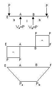
Fig.23.1
-
Fig.23.1 shows a beam EABF of negligible weight with supports at A and B, l units apart. Let the overhangs EA = BE = a.
-
A point load P be applied at each end of the beam.
-
It can be easily seen that between A and B, the B.M is constant and there is no shear force at this portion.
-
We can simply say that this portion (between A and B) is absolutely free from shear but is subjected to bending moment Wa
This condition of the beam between A and B is called pure bending or simply bending.
In the end we can conclude that A part of a member is said to be in pure bending if no shearing force exists in this part.
23.3 THEORY OF SIMPLE BENDING
In Fig.23.2 ACDB is a part of a beam of length Δx subjected to pure bending. The length Δx has deformed to the shape as shown in Fig.23.2(c).
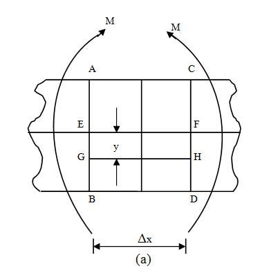
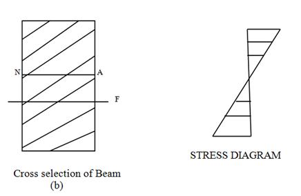
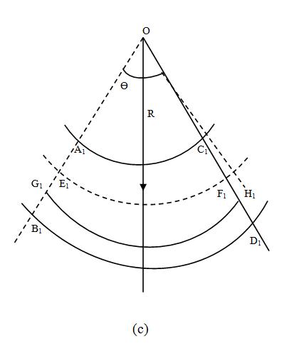
Fig. 23.2
-
The side AC has deformed to the shape A1C1. This fibre has been shortened in length. The fibre BD opposite to fibre AC has been elongated and has taken the shape B1D1. Similarly, the fibre GH has been elongated and has taken the shape G1H1.
-
Hence we can say that the beam of length Δx consists of a large number of fibres, all of them have changed their shapes; some of them have been shortened while some of them are elongated.
1. At a level between the top and bottom of the beam there will be a layer of fibres which are neither shortened nor extended.
Fibres in this layer are not stressed at all.
This layer is called the neutral layer or the neutral surface.
2. The line of intersection of the neutral surface on a cross-section is called the neutral axis.
Now if we consider all the fibres between the sections ABCD, The extremities of these fibres will remain on the planes A1B1 and C1D1 after deformation.
Let A1B1 and C1D1 meet at O and the angle between the planes A1B1 and C1D1 be Ө. Let the radius of the neutral surface be R.
Consider the fibre GH which is at a distance y from the neutral layer. Original length of the fibre GH = Δx
After deformation this fibre will deform and take the position G1H1, the new length of the fibre being (R + y) Ө.
The fibre EF in the neutral layer takes the position E1F1 without under-going any change in length. Therefore,
EF = E1F1 = Δx
Δx = RӨ
Therefore, change in length of the fibre GH = G1H1 - GH
RӨ = (R + y) Ө – Δx = (R + y) Ө – y Ө
Therefore Strain of the fibre GH = ε = \[{{changeinlength} \over {originallength}}\] = \[{{y\theta } \over {R\theta }}\]
ε = \[{y \over R}\]
Suppose the stress intensity in the fibre be f, we have strain of the fibre = ε = \[{f \over E}\]
Where E is the young’s modulus.
Therefore, ε = \[{f \over E}\] = \[{y \over R}\] or \[{f \over y}\] = \[{E \over R}\]
f = \[{E \over R}\] .y
The stress determined from the above flexure formula are called flexural stresses or bending stresses.
- From the above discussion we can conclude that all the fibres which are below the neutral layer are subjected to tensile stresses while those above the neutral layer are subjected to compressive stresses.
23.4 DERIVATION OF THE BENDING EQUATION
The bending equation is \[{M \over I}\] = \[{f \over y}\] = \[{E \over R}\]
Assumptions:
In the determination of stress in beam, the following assumptions or conditions will be applied:
The beam is initially straight and not curved.
All loads applied are steady and delivered to the beam without shock or impact.
All beams are stable under the applied loads.
Beams with constant area of cross-section with at least one axis of symmetry are to be considered.
The modulus of elasticity E is the same in tension and compression.
A plane section, taken normal to the axis of the beam, remains plane after the beam is subjected to bending.
All longitudinal elements of the beam before bending have the same length.
The stresses are within the proportional limit.
The applied loads act in a plane containing the axis of symmetry of each cross-section.
Material is homogeneous, isotropic and continuous.
Derivation:
To derive the equation of bending, Fig.23.3 shows a simply supported beam, both before bending and after bending. Two transverse sections AB and CD at a small distance dx have been considered.
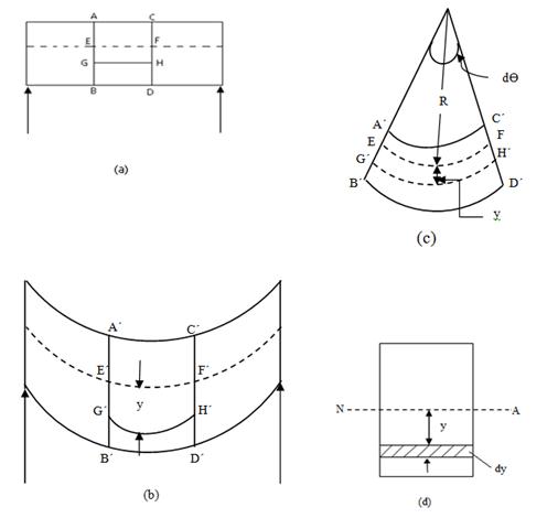
Fig. 23.3
Before bending, AC = BD = EF = GH = dx
After bending, Section AB and CD change into AꞌBꞌ and CꞌDꞌ respectively.
All the fibres above EF are shortened and fibres below EF are lengthened, in proportion to their distance from the fibre EF i.e Upper fibre get into compression and lower fibre get into tension.
- The EF layer which is between these two zones of compression and tension is neither in compression nor in tension, thus creating a neutral layer.
4. Let R be the radius of curvature of neutral layer EF, after bending. Arc EF subtends an angle dӨ at the centre of curvature, which makes EF = R dӨ and GꞌHꞌ = (R + y) dӨ.
5. Bending tensile strain in ![]()
Hence, εGH = where fy is the stress at a distance y from the neutral axis.
fy , the stress used in the expression is longitudinal and perpendicular to the cross-section. Strain produced will be in longitudinal direction.
This expression can be rewritten as
\[{{{f_y}} \over y}={E \over R}\]
Since E and R constant, For a bent beam = constant, which implies that it can be written for all points at a section depending on the distance y i.e.
\[\frac{{{f_y}}}{y} = \frac{{{f_1}}}{{{y_1}}} = \frac{{{f_2}}}{{{y_2}}} = \frac{{{f_{max}}}}{{{y_{max}}}}\]
Or fy = \[{{{f_{max}}} \over {{y_{max}}}}\] .y
It can also be concluded that stress-variation on the compression portion would be similar and the maximum bending stress will occur at extreme fibre, nature of the stress being opposite.
6. Now consider a small area dA at distance y as shown in the cross-section of beam.
Force on this elementary area dA, carrying stress fy is dF = fy.dA = \[{{{f_{max}}} \over {{y_{max}}}}\] . y dA
Moment of the force about the N.A will be dM = .y dA.y
Therefore, moments of all such forces for the entire depth will be
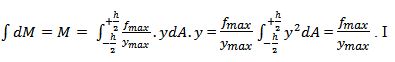
(I = moment of inertia = \[\smallint dA{y^2}\] )
Hence, = \[{M \over {I}} = {{{f_{max}}} \over {{y_{max}}}} = {{{f_y}} \over y}\]
7. Combining equation (7.1) and (7.2), the simple bending formula is obtained i.e.
It is called Simple Flexure Formula.
The word simple signifies that only pure bending is being considered.
Shear force and bending moment varies on beam from section to section.
At the point of maximum B.M, S.F is zero.
The Bending equation is applied for maximum bending moment.
- In case of Cantilever subjected to loading vertically downwards, upper fibres will be in tension while lower fibres will be in compression.
Limitations of the Flexural Formula:
While deriving the Flexural formula, certain assumptions had been made, which limits the extent of its field of application. The formula cannot be applied to cases such as
When the load on the beam is not applied perpendicularly to its longitudinal axis.
When the loads are suddenly (or with impact) applied.
When the cross-sections are unsymmetrical.
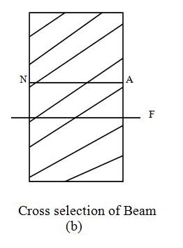
23.5 NEUTRAL AXIS
As we have discussed earlier, The neutral axis is defined as an imaginary line in the cross-section of beam along which no stresses occur.
- In other words, when a beam bent downwards, the line of zero stress below which all fibres are in tension and above which they are in compression is called neutral axis.
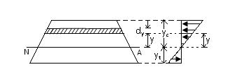
Fig.23.4
Fig.23.4 shows the cross-section of a beam. Let R be the radius of curvature of the neutral layer at this section.
Hence the stress at any point distant y from the neutral axis is given by
f = \[{E \over R}\] .y
where E is the young’s modulus. If the section be subjected to pure sagging moment, this stress will be compressive at any point above the neutral axis and tensile below the neutral axis.
Now consider an elemental area da distant y from the neutral axis.
Stress on the elemental area = f = \[{E \over R}\] .y
Therefore, Thrust on an elemental area = f da = \[{E \over R}\] .y da
Therefore, Total thrust on the beam section = \[{E \over R}\sum \limits_{{y_t}}^{{y_c}} yda\]
Since no axial load has been applied, the total thrust on the beam section equals zero.
\[{E \over R}\sum \limits_{{y_t}}^{{y_c}} yda\] = 0 , Therefore \[\sum \limits_{{y_t}}^{{y_c}} yda\] = 0
This is possible only when the neutral axis is a centroidal axis.
Example 23.1: A steel plate is bent into a circular arc of radius 15 meters. If the plate section be 100 mm wide and 15 mm thick, Find the maximum stresses induced and the bending moment which can produce this stress. Take E = 2 × 10⁵ N/mm2.
Solution: Moment of inertia of the section about the neutral axis.
I = \[{{100 \times {{15}^3}} \over {12}}\] = 28125 mm4
Bending Equation is \[{M \over I}={f \over y}={E \over R}\]
f = \[{E \over R}y\]
\[{f_{max}}={{2 \times {{10}^5}} \over {15 \times {{10}^3}}} \times \left( {{{15} \over 2}})\] N/mm2 = 100 N/mm2
M = \[{E \over R}.I\] = \[{{2 \times {{10}^5}} \over {15 \times {{10}^3}}} \times 28125\] = 37500 Nmm
Example 23.2: A thin high-strength steel plate 5 mm thick and 800 mm long is bent by couples Mo into a circular arc which subtends a central angle of 45°. Find the maximum bending stress in the plate. If the central angle is increased will the stress increase or decreases?
Take E = 2 × 10⁵ N/mm2 .
Solution: Let R be the radius of the neutral layer
L = Rθ
R = \[{L \over \theta }\] = \[{800} \over {\left( {{\Pi \over 4}} \right)}}\] = \[{{3200} \over \Pi }\] mm
\[{E \over R}\] = \[{f \over y}\] , therefore f = \[{E \over R}\] .y
f = \[{{2 \times {{10}^5}} \over {\left( {{{3200} \over \Pi }} \right)}}\] ×\[{E \over R}\] = 490.87 N/mm2
Example 23.3: Fig. 23.5 shows a rectangular tube section of an aluminium alloy whose ultimate stress is 350 N/mm2. Determine the bending moment for which the factor of safety will be 3. Find also the corresponding radius of curvature. Take E = 7 × 10⁴ N/mm2.
Solution: Allowable bending stress = f = \[{350 \over 3}\] = 116.67 N/mm2
Moment of Inertia of the section = I = \[{{60 \times {{100}^3}} \over {12}} - {{50 \times {{90}^3}} \over {12}} = 1962500\]
Allowable B.M. = M = \[{f \over {{y_{max}}}}.I = {{116.67} \over {50}}\left( {1962500})\] Nmm
= 4.579 × 106 = 4.579 kNm
Radius of Curvature = R = \[{E \over f}.{y_{max}}\]
= \[{{7 \times {{10}^4}} \over {116.67}} \times 50\] = 29999.14 mm
= 29.999 m
Example 23.4: A copper wire of 2 mm diameter is bent into a circle and held with its ends just in contact (Fig.23.6). If the maximum permissible strain in copper is 0.0025, find the shortest length of the wire that can be used.
Solution: Let the minimum radius of the circle be R
Let f be the maximum stress in the wire.
\[\frac{f}{{\left({\frac{d}{2}}\right)}}=\frac{E}{R}\]
Therefore \[{d \over {2R}} = {f \over E} = 0.0025\]
\[2 \over {2R}} = 0.0025\]
R = 400 mm
= 2ΠR = 2Π × 400 = 2513.27 mm
Last modified: Wednesday, 11 September 2013, 10:30 AM