Site pages
Current course
Participants
General
MODULE 1. BASIC CONCEPTS
MODULE 2. SYSTEM OF FORCES
MODULE 3.
MODULE 4. FRICTION AND FRICTIONAL FORCES
MODULE 5.
MODULE 6.
MODULE 7.
MODULE 8.
19 April - 25 April
26 April - 2 May
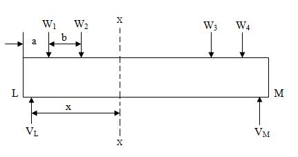
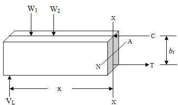
LESSON 24.
24.1 MOMENT OF RESISTANCE
(A)
(B)
(C)
Fig.24.1
Bending equation gives or \[{M \over {I}} = {{{f_{all}}} \over {{y_{max}}}}\] or M = \[{I \over {{y_{max}}}}\] fall
MR = Z fmax
This quantity "ZF" is termed as "Moment of Resistence", which totally depends on allowable stress fall ans section modules Z.
It does not depend on the system of loading.
However, it would be necessary that moment of resistence is always greater than or equal to the external bending moment.
24.2 SECTION MODULUS
It is a property of sectional area.
We know that \[{M \over {I}} = {f \over y}\]
Or f = \[{M \over {I/y}}\] and fmax = \[{M \over {I/{y_{max}}}}\]
Where \[{I \over {{y_{max}}}}\] is called section modulus ‘Z’.
Therefore Z = \[{I \over {{y_{max}}}}\]
fmax = \[{M \over Z}\] which is similar to f = \[{P \over A}\] (in simple tension and compression)
For same area of cross-section, but with different shapes, the section modulus will be different.
In bending it would be desirable to choose sections which give the maximum value of section modulus.
I sections have been found to give the maximum section modulus for a specific area of cross-section and hence should be preferred for bending loads.
7.8 SECTION MODULUS FOR VARIOUS SHAPES OF BEAM SECTIONS
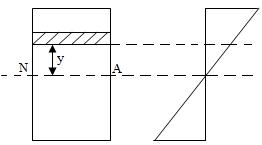
(i) Rectangular Section
Fig.24.2 shows a rectangular section of width b and depth d. Let the horizontal centroidal axis be the neutral axis.

Fig.24.2
Section Modulus = Z = \[{{Moment of inertia about the neutral axis} \over {Distance of most distant point from the neutral axis}}\]
= \[{I \over {{y{max}}}}\]
I = \[{{b{d^3}} \over {12}}\] and ymax = \[{d \over 2}\]
Z = \[{{b{d^3}} \over {12}}\] . \[{2 \over d}\] = \[{{b{d^2}} \over {6}}\]
Let f be the maximum stress offered by the beam section.
Therefore moment of resistance = M = f Z = f \[{{b{d^2}} \over {6}}\]
Or M = \[{1 \over 6}\] f bd2
(ii) Hollow Rectangular Section
Fig.24.3 shows a hollow rectangular section. Let the overall width and depth be B and D. Let the width and depth of the centrally situated rectangular hole be b and d.
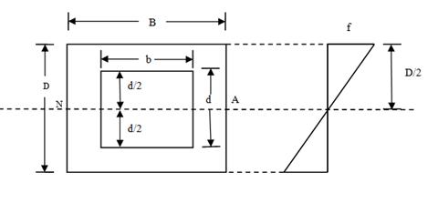
Fig.24.3
Moment of inertia about the neutral axis = I = \[{{B{D^3}} \over {12}}\] - \[{{b{d^3}} \over {12}}\] = \[{1 \over 12}\] [BD3 - bd3]
ymax = \[{D \over 2}\]
Therefore, Section Modulus = Z = \[{I \over {{y_{max}}}}={1 \over {12}}(B{D^3}-b{d^3}\] ) \[{2 \over D}\]
Z = \[{{B{D^3} - b{d^3}} \over {6D}}\]
If f be the maximum bending stress the moment of resistance = M = f Z
M = \[{1 \over 6}f\left( {{{B{D^3} - b{d^3}} \over D}} \right)\]
(iii) Circular Section
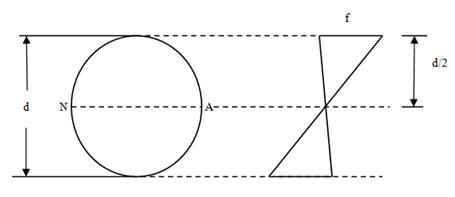
Fig. 24.4
Let the diameter of the section be d. Moment of inertia of the section about the neutral axis = I = \[{{\pi{d^4}} \over {64}}\]
ymax = \[{d \over 2}\]
Section Modulus = Z = \[{I \over {{y_{max}}}}\] = \[{{\pi{d^3}} \over {32}}\]
If f be the stress offered by the section, the moment of resistance = M = f Z
= f \[{{\pi{d^3}} \over {32}}\]
(iv) Hollow Circular Section
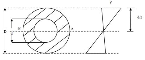
Fig.24.5
Fig.24.5 shows a hollow circular section of external diameter D and internal diameter d.
Moment of inertia about the neutral axis = I = \[{\pi\over {64}}\left[ {{D^4} - {d^4}} \right]\]
ymax = \[{D \over 2}\]
Therefore, section modulus = Z = \[{I \over {{y_{max}}}}\] = \[{{\pi \left({{D^4} - {d^4}} \right)} \over {32D}}\]
If f be the maximum stress offered by the section, the moment of resistance = M = f Z
M = f \[{{\pi \left({{D^4} - {d^4}} \right)} \over {32D}}\]
Example 24.1: Fig.24.6 shows the section of a tube of aluminium alloy. Determine the maximum moment that can be applied to the tube if the permissible bending stress is 100 N/mm2. Find also the radius of curvature of the tube as it bends. Take E = 72800 N/mm2.
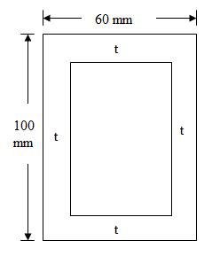
Fig.24.6
Solution: Moment of Inertia of the section,
I = \[{{60 \times {{100}^3}} \over {12}} - {{50 \times {{90}^3}} \over {12}} = 1962500\]
= 1962500 mm4
Maximum moment on the section, M = \[{f \over {{y_{max}}}}.I = {{100 \times 1962500} \over {50}}\] Nmm
= 3925000 Nmm
Radius of Curvature, R = \[{{EI} \over M} = {{72800 \times 1962500} \over {3925000}}\] mm
= 36400 mm
Example 24.2: A cast iron test beam 25mm × 25mm in section and 2 m long and supported at the ends fails when a central load of 700N is applied. What uniformly distributed load will break a cantilever of the same material 55mm wide, 110mm deep and 3m long?
Solution: Let us first consider the test beam.
Maximum bending moment = M = \[{{WL}\over 4}={{700\times 2}\over 4}\times 1000Nmm\] = 35 × 104 Nmm
Moment of Resistance, R = \[{1 \over 6}.fb{d^2}\] = \[{1 \over 6}.f \times 25 \times {25^2}\] = \[{{15625} \over 6}f = 2604.17fNmm\]
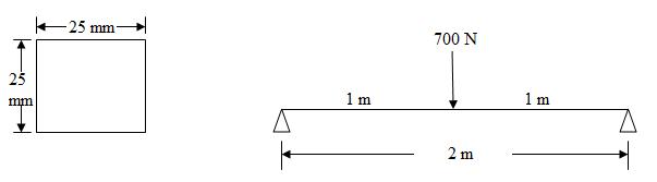
Fig.24.7
Equating the moment of resistance to the maximum bending moment
\[2604.17f=\] 35 × 104
f = \[{{35{\rm{}} \times {\rm{}}{{10}^4}{\rm{}}} \over {2604.17}}\] = 134.39 N/mm2
Now let us consider the cantilever.
Let the distributed load on the cantilever be w N/m run so as to break it.
Therefore, maximum bending moment = M = \[{{w{l^2}} \over 2} = {{w \times {3^2}} \over 2} \times 1000Nmm\] = 4500w N mm
Moment of Resistance of the section = \[{1 \over 6}.fb{d^2} = {1 \over 6} \times 134.39 \times 55 \times {110^2}Nmm\]
= 14.91 × 10⁶ N mm
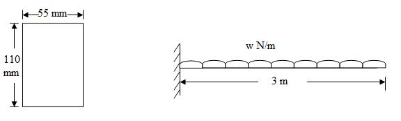
Fig.24.8
Equating the maximum bending moment to moment of resistance we have,
4500 w =14.91 × 10⁶
w= 3313 N/m
Example 24.3: A machine component of semi circular section 300mm diameter acts as a beam of span 1.50m. It is placed with its base horizontal. If it carries a uniformly distributed load of 150kN/m run on the whole span, find the maximum stress induced.
Solution: Moment of inertia of the section about the neutral axis = I = 0.00686 d4
Extreme fibre distance from the neutral axis = r - \[{{4r} \over {3\Pi }} = {{3\Pi- 4} \over {4\Pi }} \times r = 0.5756\]
r = 0.2878 d
Section modulus, Z = \[{{0.00686{d^4}} \over {0.2878d}} = 0.0238{d^3}\]
Maximum bending moment, M = \[{{300 \times {{1.50}^2}} \over 8} = 84.375kNm\]
Maximum bending stress \[{f_{max}}={M \over Z}={{84.375\times{{10}^6}}\over{0.0238\times{{300}^3}}}=131.30\] N/mm2
Example 24.4: Find the safe concentrated load that can be applied at the free end of a 2m long cantilever. The section of the cantilever is a hollow square of external side 50mm and internal side 40mm the safe bending stress for the material being 65 N/mm2.
Solution: Moment of inertia of the section of the cantilever,
I = \[{{{{50}^4}} \over {12}}-{{{{40}^4}} \over {12}}=307500\] mm4
Section modulus, Z = \[{I \over {{y_{max}}}}={{307500} \over {30}}\] = 10250 mm3
Let the safe concentrated load at the free end be W Newton
Maximum B.M, M = W × 2 × 1000 = 2000 W Nmm
M = f Z, 2000 W = 65 × 10250
W = \[{{65 \times 10250} \over {2000}}=\] 333.125 N
Example 24.5: The moment of inertia of a beam section 450mm deep is 60.5 × 107 mm4. Find the span over which a beam of this section, when simply supported, could carry a uniformly distributed load of 45kN per meter run. The flange stress in the material is not to exceed 110 N/mm2.
Solution: Section modulus of section = Z = \[{I \over {{y_{max}}}} = {{60.5 \times {{10}^7}} \over {250}}\]
Therefore, Z = 24.2 × 105 mm3
Let the maximum span be l meter.
Therefore, maximum bending moment = M = \[{{w{l^2}} \over 8}={{45000\times{l^2}} \over 8} \times 1000Nmm\]
= 56.25 × 10⁵ l2 N mm
Moment of resistance of the section corresponding to the maximum bending stress of 110 N/mm2
= f Z = 110 × 24.2 × 105 N mm
Equating the maximum bending moment to the moment of resistance, we get
56.25 × 10⁵ l2 = 110 × 24.2 × 105
l2 = \[{{110\times 24.2\times{{10}^5}} \over {56.25\times{{10}^5}}}=47.32\]
Therefore, l = 6.88 m, say 7 m
Last modified: Wednesday, 11 September 2013, 6:30 AM