Site pages
Current course
Participants
General
MODULE 1. BASIC CONCEPTS
MODULE 2. SYSTEM OF FORCES
MODULE 3.
MODULE 4. FRICTION AND FRICTIONAL FORCES
MODULE 5.
MODULE 6.
MODULE 7.
MODULE 8.
19 April - 25 April
26 April - 2 May
LESSON 26.
26.1 TORSION
Torsion refers to twisting of a straight member under the action of a turning moment or torque which tends to produce a rotation about the longitudinal axis. Some examples of torsion are steering rod, propeller shafts etc.
- A torque is composed of a couple acting in a plane perpendicular to the longitudinal direction of the shaft.
26.2 THEORY OF PURE TORSION
Fig.26.1 shows a solid cylindrical shaft of radius R and length l subjected to a couple or twisting moment T at one end, while its other end is held or fixed by the application of a balancing couple of the same magnitude.
Let LM be a line on the surface of the shaft and parallel to the axis of the shaft before the deformation of the shaft. As an effect of torsion this line, after the deformation of the shaft, takes the form LN.
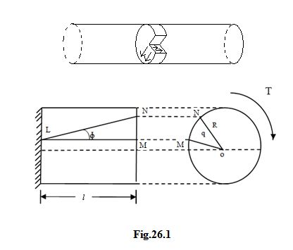
The angle NLM = ϕ represents the shear strain of the shaft material at the surface. This angle being small, we have ,
MN = l ϕ , Therefore ϕ = \[{{MN} \over l}\] -------------------------------(i)
Let the angle MON be the angular movement of the radius OM due to the strain in the length of the shaft. Let MON = Ө. Let fs be the shear stress intensity at the surface of the shaft.
We know, fs = ϕ C ------------------------------------(ii)
Where C = Modulus of rigidity of the shaft material
fs = \[\left( {{{MN} \over l}} \right)\] C
But MN = R Ө, Therefore fs = \[{{R\theta } \over l}\] . C
So, \[{{{f_s}} \over R}\] = \[{{C\theta } \over l}\] -------------------------------------(iii)
Since C, Ө and l are constants, it follows that at any section of the shaft, the shear stress intensity at any point is proportional to the distance of the point from the axis of the shaft. Hence the shear stress is maximum at the surface and shear stress is zero at the axis of the solid shaft. Fig.26.2 shows the shear stress distribution for a solid shaft and a hollow shaft.

Longitudinal Shear stresses
It is also important to realize that the shear stresses acting on the cross-sectional planes are accompanied by shear stresses of the same magnitude in the longitudinal planes following the principle of complementary shear stresses. See fig.--------
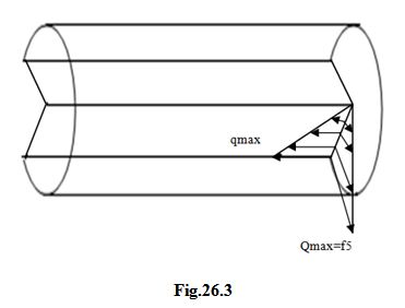
Fig.26.3
Suppose the material is weaker in longitudinal shear than on the cross-sectional planes, the first formation of cracks will appear in the longitudinal direction on the surface.
26.3 TORSIONAL MOMENT OF RESISTANCE
Fig.26.4 shows the section of the shaft of radius R subjected to pure tension. Let fs be the maximum shear stress which occurs at the surface.
Consider an element area da at a distance r from the axis of the shaft.
Shear stress offered by the elemental area = q = \[{r \over R}\] fs
Therefore, Shear resistance offered by the elemental area q. da = \[{r \over R}\] fs. da
Moment of resistance offered by the elemental area = \[{r \over R}\] fs. da . r = \[{{{f_s}} \over R}da.{r^2}\]
Therefore, total moment of resistance offered by the cross-section of the shaft = T
= \[{{{f_s}} \over R}\] ∑ da. r2
But ∑ da. r2 represents the moment of inertia of the shaft section about the axis of the shaft, i.e, the quantity ∑ da. r2 is the polar moment of inertia Ip of the section of the shaft.
T = \[{{{f_s}} \over R}\] . Ip , \[{T \over {{I_p}}} = {{{f_s}} \over R}\] ----------------------------------------(iv)
But from eqn. (iii), \[{{{f_s}} \over R}\] = \[{{C\theta } \over l}\] , Therefore \[{T \over {{I_p}}} = {{{f_s}} \over R}\] = \[{{C\theta } \over l}\]
Polar Moment of inertia of a circular shaft
Solid shaft : Radius R, Diameter D
Ip = \[{\pi{{R^4}} \over 2}\] = \[{\pi{{D^4}} \over {32}}\]
Hollow shaft : Outer radius R1, Inner radius R2
Outer diameter D1, Inner diameter D2
Ip = \[{\pi \over 2}\left[ {{R_1}^4 - {R_2}^4} \right]\] = \[{\pi \over {32}}\left[ {{D_1}^4 - {D_2}^4} \right]\]
Alternatively, if Rm = Mean radius and Dm = Mean diameter and t = wall thickness
Ip = \[{\pi{{R_m}t} \over 2}\left[ {4{R_m}^2 + {t^2}} \right]\] = \[{\pi{{D_m}t} \over 4}\left[ {{D_m}^2 + {t^2}} \right]\]
For the case when t is very small
Ip = 2П \[{R_m}^3t\] = \[{\pi{{D_3}^3t} \over 4}\]
Assumptions in the Theory of Pure Torsion
(i) The material of the shaft is uniform throughout.
(ii) The twist along the shaft is uniform.
(iii) The shaft is of uniform circular section throughout.
(iv) Cross-section of the shaft, which are plane before twist remain plane after twist.
(v) All radii which are straight before twist remain straight after twist.
Last modified: Wednesday, 11 September 2013, 7:21 AM