Site pages
Current course
Participants
General
Module 1. Hydraulic Basics
Module 2. Hydraulic Systems
MODULE 3.
MODULE 4.
MODULE 5.
MODULE 6.
MODULE 7.
MODULE 8.
19 April - 25 April
26 April - 2 May
LESSON 16. Hydraulic Circuits
16.1 Introduction
A hydraulic control system is used to control position / speed of a load and provide necessary force for doing work. This is achieved by designing and building appropriate hydraulic circuits required for operating some kind of a hydraulic machine or hydraulic power system. A hydraulic circuit includes various components like reservoir, pump, actuator, motor, pipes, hoses, clamps, accumulator, valves, intensifier etc. These components can be arranged in number of ways to get the desired output from the hydraulic circuit. There may be different types of hydraulic circuits as discussed in the following sections.
16.2 Speed Control Circuits
In hydraulic operated machine tools and other mechanical equipment, speed control is required to enhance the functional versatility of the machine. Speed control required during different strokes can be done by regulating oil flow to the cylinder. Speed control of a single load can be done using variable displacement pump. If the speeds of a number of loads are to controlled independently, the metering of the oil to individual cylinders is done by using flow control valves. Depending upon the location of flow control valve for metering the oil, speed control circuits can be classified as meter-in, meter-out and bleed-off circuits.
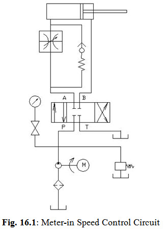
16.2.1 Meter-in Speed Control
This type of circuit consists of a pressure compensated flow control valve between the pump and cylinder. This flow-control valve is placed in pressure line that actuates the cylinder to work. Oilflowing into the work cylinder is metered through the flow-control valve. Since this metering action involves reducing flow from a pump to the cylinder, the pump must deliver more fluid than is required to actuate the cylinder at the desired speed. Excess fluid returns to the tank through a relief valve. To conserve power and avoid undue stress on the pump, the relief valve pressure is kept little higher than the working pressure. A meter-in circuit is considered to be better in applications where a load always offers a positive resistance to flow during a controlled stroke.These circuits are used where slow feed rates are required. A meter-in speed control is shown in Fig. 16.1.
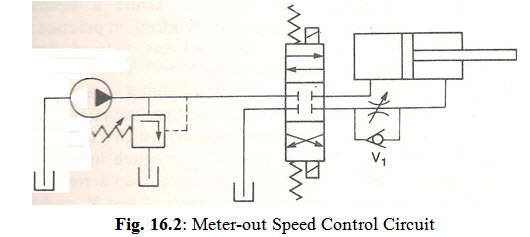
16.2.2 Meter-out Speed Control
In this type of circuit, a flow-control valve is installed on the return side of a cylinder so that it controls the cylinder actuation speed by metering its discharge flow. A relief valve is kept a little above the operating pressure which is required by the type of application. These types of circuit are best suited where work resistance is negative such as climb milling. These circuits may also be used for overhauling load applications in which a workload tends to pull an operating piston faster than pump delivery,like in drilling, reaming, boring, turning machines. A flow-control-and-check valve used in this circuit would allow reverse free flow. A meter out speed control circuit is shown in Fig. 16.2.
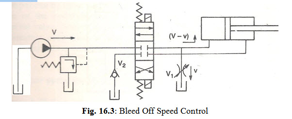
16.2.3 Bleed Off Speed Control
In this type of circuit flow control valve is not directly provided in the feed line but is connected to the pressure side as shown in Fig. 16.3. The flow control valve regulates flow to a cylinder by diverting a portion of a pump flow to the tank. This type of circuit usually involves less heat generation because pressure on a pump equals the work resistance during a feed operation. This type of circuit is used for constant load applications.
16.3 Pressure Compensated Circuit
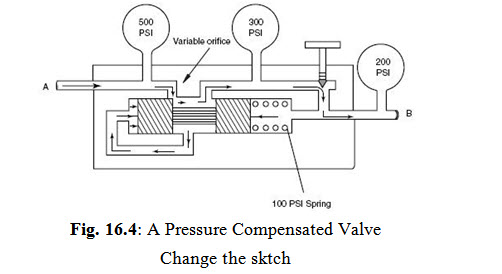
Flow rate through flow control valves can vary if either the fluid pressure or the temperature changes. In some cases where precise control of actuator speed is needed, a true flow control valve is required which delivers a fixed flow regardless of the line pressure or fluid temperature. For such cases, a compensated flow-control valve is used. This valve automatically changes the adjustment or pressure drop. A compensated flow-control valve is used mainly to meter fluid flowing into a circuit. A pressure compensated valve is shown in Fig. 16.4. A piston is subjected to pressure on the two sides of the orifice meant for flow control. The orifice setting is done with the help of adjustable screw. The net force on the piston balances the spring force set as per flow requirement. If the line pressure changes, the piston moves to the left or right thereby modulating the area of the variable orifice. This piston thus helps in maintaining a constant pressure drop across the flow control valve orifice, which implies a constant flow through the valve.
16.4 Pressure Reducing Circuit
This type of circuit is normally utilized where two branches of a circuits are working at different pressures. In this one of the cylinder receives the pressure fluid from direction control valve in forward stroke where as other cylinder receives pump pressure through pressure reducing valve. The pressure of first cylinder will depend upon the relief valve setting. The pressure in the second cylinder can be adjusted by pressure reducing valve. A pressure reducing valve is shown in Fig. 16.5.
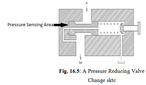
A spring loaded spool senses the outlet pressure. If the force on the spool is more than the spring force, the spool moves towards right, thereby reducing the oil flow to the output side.Flow through the small bleed hole in the spool to the spring chamber and drain prevents the valve from closing completely.
16.5 Sequencing Circuit
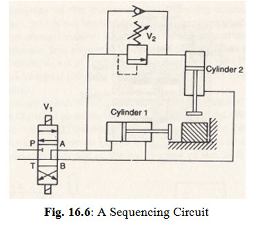
Cylinders may be sequenced by restricting flow to one cylinder. This type of circuit is used where there are two cylinders and are to be operated in sequence. One method of restricting flow is with backpressure check valves. They prevent flow until a set pressure is reached. In this circuit, cylinder one extends and retracts ahead of cylinder two. This circuit is mainly comprised of a sequence valve which allows the flow into cylinder one (1) and then to the cylinder two (2) as shown in Fig. 16.6.
16.6 Intensifier
A hydraulic intensifier or booster is a device that converts low pressure from a large area of the intensifier into high pressure in a small area of the intensifier. An intensifier consists of two different-sized cylinders connected by a common piston.The force exerted on the smaller side is the same as that on larger side, but the pressure exerted on the smaller cylinder get intensified due to different sizes of pistons. An air-oil intensifier is shown in Fig. 16.7.
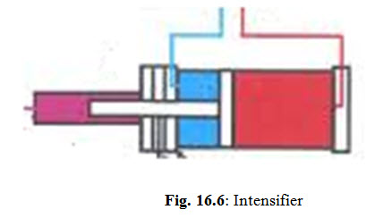
The large-area air piston pushes a small-area hydraulic ram against trapped oil. The difference between the two areas gives high-pressure capability at the small ram. This capability is indicated by the area ratio. If the air piston has a 5-in. diameter and the oil piston has a 1-in. diameter, the area ratio is 25:1. With this area ratio, 80 psi acting on the air piston produces 2000 psi at the hydraulic piston.
16.7 Reciprocating Circuit
The back-and-forth extension and retraction of a hydraulic cylinder is called reciprocation of a piston in the cylinder. This type of circuit can be utilized in number of machines, like shaper machine, punch press etc. In the punch press there is a single hydraulic cylinder that extends and retracts and the required work is done with the help of single cycle cylinder reciprocation.
Last modified: Saturday, 15 March 2014, 10:12 AM