Site pages
Current course
Participants
General
Module 1. Hydraulic Basics
Module 2. Hydraulic Systems
MODULE 3.
MODULE 4.
MODULE 5.
MODULE 6.
MODULE 7.
MODULE 8.
19 April - 25 April
26 April - 2 May
LESSON 22. Design of Vane Pump
22.1 Introduction
Vane pumps are the rotary type of pump which are fitted in the hydraulic systems. In these pumps there is hardly any slippage and the quantity of fluid pumped is nearly same for each rotation of shaft. These are generally positive displacement pumps
22.2 Design of Gear Pump
Gear pump consists of a driving gear and a driven gear enclosed in a closely fitted housing. The gears rotate in opposite directions . Both sets of teeth project outward from the center of the gears. As the teeth of the two gears separate, a partial vacuum forms and draws liquid through an inlet port . Liquid is trapped between the teeth of the two gears and the housing so that it is carried and a force is developed which drives a liquid through an outlet port. Volume of fluid can be calculated as-
Volume of fluid
Let V = volume of fluid
D1 = outer diameter of gear teeth
D2 = inner diameter of gear teeth
N = speed of pump (rpm)
w = gear teeth width
Therefore volume displaced in one revolution V = \[\frac{\pi }{4}(D{1^2} - {\text{}}D{2^{2{\text{}}}})\] x w
Discharge of pump
Discharge per sec . Q = VxN
Efficiency
Efficiency \[\eta\] = \[\frac{{Qa}}{{Qt}}x100\]
Qa = actual discharge
Qt = theoretical discharge
22.3 Vane Pump Design Calculations
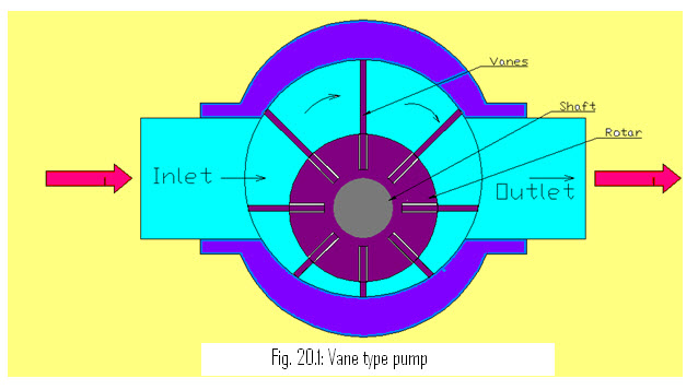
The rotary vane pump is consisted of rotor and stator. The stator is the stationary enclosure in which the rotor rotates. The rotor is mounted with eccentric and therefore the rotor makes contact with the stator at the top of the stator between the inlet and the outlet. This point is called the contact point and is actually in close contact separated only by a thin film of oil. The sliding vanes move in and out of the rotor, making contact with the stator surface. The vanes can be spring-loaded or slide by centrifugal force. These are high volume pumps which can pump at higher pressures .When the rotor rotates within the stator , at the inlet of the pump one of the ffallows the fluid to to enter the pump. As it enters inside the pump, the fluid is trapped between the rotor vanes and the stator during rotation, it is pushed out through the outlet of the pump.
22.4 Volumetric Displacement
It can be defined as the product of area and width of rotar. It can be given as-
Let Dc = diameter of cam ring/stator
Dr = diameter of rotor
e = eccentricity
N = speed (rpm)
w = width of rotor
Maximum eccentricity can be given as
emax = \[\frac{{{\text{Dc}} - {\text{Dr}}}}{2}\]
Now volumetric displacement will be- \[A = \pi {r^2}\]
Vd = \[\frac{\pi }{4}(D{c^2} - D{r^2})\] x w
= \[\frac{\pi }{4}(Dc - Dr)\] (Dc + Dr ) x w
= \[\frac{\pi }{4}(Dc + D{r^2})\] x 2emax x w
= \[\frac{\pi }{4}(Dc + D{r^2})\] x emax x w
22.5 Cavitation
Pump cavitation is the formation and subsequent collapse of vapor bubbles in a pump. It occurs when the absolute pressure on the liquid falls below the liquid vapor pressure. When the vapor bubbles collapse with high frequency, it sounds like marbles are moving through the pump. It causes wear and tear and damage to the pump.
22.6 Aeration
Aeration is the presence of air in the hydraulic fluid . It causes the fluid to appear milky and components are to operating erratically. It is because of the compressibility of trapped air in the fluid.
Last modified: Tuesday, 18 March 2014, 5:18 AM