Site pages
Current course
Participants
General
MODULE 1. Overview of renewable energy sources
MODULE 2. Characterization of Biomass
MODULE 3. Thermochemical conversion Technology (TCCT)
MODULE 4. Biochemical conversion Technology-Biogas...
MODULE 5. Bio-fuels (BCCT)
MODULE 6. Solar Energy Conversion System (SECS)
MODULE 7. Hydro-Energy Conversion System (HECS)
MODULE 8. Wind Energy Conversion System (WECS)
MODULE 9. Ocean Energy Conversion System (OECS)
MODULE 10. Energy conservation in agriculture
LESSON 6. Biomass Combustion Technology
Combustion
Biomass combustion is a complex process that consists of consecutive heterogeneous and homogeneous reactions. The main process steps are drying, devolatilization, gasification, char combustion, and gas-phase oxidation. The time used for each reaction depends on the fuel size and properties, on temperature, and on combustion conditions. Batch combustion of a small particle shows a distinct separation between a volatile and a char combustion phase with time. For the design of combustion appliances, the high content of volatiles (80% to 85%) needs to be respected. For large particles, the phases overlap to a certain extent. Nevertheless, even for log wood furnaces, a certain separation of distinct combustion regimes with time can be found. Since automatic combustion systems are operated continuously, the consecutive reactions occur simultaneously at different places in the furnace (e.g., in different sections on and above a grate). Hence the zones for different process steps during combustion can be optimized by furnace design.
A distinct separation of different process steps can be advantageous with respect to pollutant formation. The main combustion parameter is the excess air ratio (ì) that describes the ratio between the locally available and the stoichiometric amount of combustion air. For typical biomass, the combustion reaction can then be described by the following equation if fuel constituents such as N, K, Cl, etc., are neglected:
CH1.44O0.66 + ì1.03 (O2 + 3.76 N2)
f intermediates (C, CO, H2, CO2, CmHn, etc.)
f CO2 + 0.72H2O + (ì - 1)O2+ ì3.87N2(-439 kJ/kmol)
Where, CH1.44O0.66 describes the average composition of typical biomass used for combustion, i.e., wood, straw, or similar material. As a result of the combustion process, different types of pollutants can be distinguished:
Unburntpollutants such as CO, CXHY, PAH, tar, soot, unburnt carbon, H2, HCN, NH3, and N2O;
Pollutants from complete combustion such as NOX (NO and NO2), CO2, and H2O; and
Ash and contaminants such as ash particles (KCl, etc.), SO2, HCl, PCDD/F, Cu, Pb, Zn, Cd, etc.
Staged Combustion
If staged combustion isapplied, the excess air can vary in different sections.Two-stage combustion is applied with primary airinjection in the fuel bed and consecutive secondary airinjection in the combustion chamber.Thisenables good mixing of combustion air with the combustiblegases formed by devolatilization and gasificationin the fuel bed. If good mixing is ascertained, anoperation at low excess air is possible (i.e., excess airì < 1.5) thus enabling high efficiency on one hand andhigh temperature with complete burnout onthe other hand.If good mixing is achieved,the concentrations of unburnt pollutants can be reducedto levels close to zero (e.g., CO < 50 mg/m3 and CXHY<5 mg/m3 at 11 vol % O2). However, an accurate processcontrol is needed to ensure optimum excess air inpractice. For this purpose, self-adjusting control systemswith use of sensors for CO and ì (CO/ì-controller) orof CO and temperature have been developed.Air staging applies air injection at two levels as well. In addition to conventional two-stage combustion, primary air needs to be understoichiometric (ì primary <1). Further, a relevant residence time (and hence a reduction zone in the furnace thus leading to an enlarged furnace volume) is needed between the fuel bed and the secondary air inlet. In fuel staging, fuel is fed into the furnace at two different levels. The primary fuel is combusted with excess air > 1. A consecutive reduction zone is achieved by feeding secondary fuel and late inlet of final combustion air for the secondary fuel. Both air staging and fuel staging have been developed as primary measures for in-situ reduction of fuel NOX in biomass combustion and are described below.

Unburnt Pollutants
The main needs for completeburnout are temperature, time, and turbulence(TTT). The mixing between combustible gases and aircan be identified as the factor that is mostly limitingthe burnout quality, while the demands for temperature(around 850 °C) and residence time (around 0.5 s) caneasily be achieved. Sufficient mixing quality can beachieved in fixed bed combustion by the above-describedtwo-stage combustion. In fluidized bed, good mixing isachieved in the bed and the freeboard and also dustcombustion enables good mixing.For future improvements in furnace design, computationalfluid dynamics (CFD) can be applied as astandard tool to calculate flow distributions in furnaces,as shown by an example. Furthermore,the reaction chemistry in the gas phase can be implementedin CFD codes.14,15 However, the heterogeneous reactions during drying, transport, devolatilization, andgasification of solid biomass before entering the gasphasecombustion need to be considered as well andneeds further improvement to enable the application ofwhole furnace modeling. NOX Emissions. In combustion processes, NOand NO2 (summarized as NOX) Can be formed in threedifferent reactions. Thermal NOX and prompt NOX areformed from nitrogen in the air at high temperaturesand in the case of prompt NOX in the presence ofhydrocarbons. Further, fuel NOX can be formed fromnitrogen-containing fuels. For biomass combustion, fuelboundnitrogen is the main source of NOX emissions,while thermal and prompt NOX are not relevant due torelatively low temperatures as has been shown bytheoretical and experimental investigations.4,18Fuel nitrogen is converted to intermediate componentssuch as HCN and NHi with i ) 0, 1, 2, 3. Thesecan be oxidized to NOX if oxygen is available, which isthe case in conventional combustion. If no oxygen ispresent, intermediates can interact in the reductionzone and form N2 in reactions such as NO + NH2 ) N2+ H2O. During the past 10 years, stagedcombustion technologies have been developed as aprimary measure for process internal NOX reductionbased on this concept, thus leading to the abovedescribedtechniques of air staging and fuel staging. Both measures enable a NOX reductionon the order of up to 50% for wood with low and up to 80% for bio fuels with high nitrogen content. However, different specific conditions have to be met accurately to exhaust this reduction potential. In the case of air staging, a primary air excess around 0.7, a temperature in the reduction zone of 1150 °C and a residence time of 0.5 s are needed. The relatively high temperature can limit the application in practice due to undesired ash softening and deposit formation. For fuel staging, similar results are achieve at lower temperature, i.e., already at temperatures as low as 850 °C.22 However, the furnace concept and operation is more complex due to the need of two independent fuel feeding systems. Nevertheless, a pilot plant based on this concept has been successfully realized with a combination of understoker furnace and entrained flow reactor. For both types of staged combustion, accurate process control is needed to ensure an operation at the excess air ratio needed in the different zones.
Besides primary measures, secondary measures are available for NOX abatement. The most relevant techniques are selective non-catalytic reduction (SNCR) and selective catalytic reduction (SCR) using the same reaction as mentioned for staged combustion, i.e., NO + NH2 ) N2 + H2O. However, urea or ammonia is injected as reducing agent and as source of NH2. SNCR has to be applied in a narrow temperature windowaround 820 °C to 940 °C, thus enabling a NOX reductionup to 90%.24 SCR is typically applied in the flue gas ina temperature range around 250° to 450 °C and enablesa NOX reduction of more than 95%.24 However, relevantconcentrations of undesired side products such asHNCO, N2O, NH3, HCN, and others can be formed inboth types of secondary measures under unfavorableconditions. Hence, primary measures are preferable ifthey can achieve sufficient emission reduction.
Particulate Emissions
Biomass combustionleads to relatively high emissions of particulates, i.e.,well above 50 mg/m3 at 11 vol % O2.4,25 The majority ofthe particulates are smaller than 10 ím (i.e., particulatematter PM 10) with a high share of submicron particles(PM 1). The composition of submicron and supermicron particles in fluidized bed combustion is distinctive as the fine particles are composed mainly of K, Cl, S, Na, and Ca and the coarse particles of Ca, Si, K, S, Na, Al, P, and Fe.30 In fixed bed combustion, increasing mass concentrations of particulate emissions are typically related to increasing mean diameter.31 Further, a dependency of the particle composition on size can also be found in fixed bed conditions, as K, S, Cl, and Zn are mainly found in the submicron fraction, while the content of Ca is increasing with increasing particlesize.32 If almost complete burnout is achieved by appropriatefurnace design, the particulates result almostexclusively from ash components in the fuel with saltssuch as KCl as main components.33 The main fuelconstituents with respect to aerosol formation aretypically K, Cl, S, Ca, Na, Si, P, Fe, and Al. Primarymeasures which can safely meet a high reductionpotential, i.e., by at least a factor of 10, of this categoryof aerosols are not known so far.
Combustion Technologies
Biomass combustion is mainly used for heat production in small and medium scale units such as wood stoves, log wood boilers, pellet burners, automatic wood chip furnaces, and straw-fired furnaces. Distinct heating systems are often in the size range from 0.5 MWth to 5 MWth with some applications up to 50 MWth. Combined heat and power production (CHP) with biomass is applied by steam cycles (Rankine cycle) with steam turbines and steam engines and organic Rankine cycles (ORC) with typical power outputs between 0.5MW and 10 MW.35 Stirling engines (10 kW to 100 kW) and closed gas turbines are in development or demonstration mode. Co-firing in fossil-fired power stations enables the advantages of large size plants (>100 MW), which are not applicable for dedicated biomass combustion due to limited local biomass availability.
The systems canbe distinguished by the flow conditions in the furnace,thus describing fixed bed combustion, fluidized bed, andentrained flow or dust combustion. To achieve complete burnout and high efficiencies in small scale combustion, downdraft boilers with inverse flow have been introduced, which apply the two-stage combustion principle described above. An operation of log wood furnaces at very low load should be avoided as it can lead to high emissions of unburnt pollutants. Hence, it is recommended to couple log wood boilers to a heat storage tank. Since wood pellets are well suited for automatic heating at small heat outputs as needed for todays buildings, pellet furnaces are an interesting application with growing propagation. They are applied both as stoves and as boilers. Understoker furnaces are mostly used for wood chips and similar fuel with relatively low ash content while grate furnaces can also be applied for highash and water content.
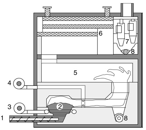
Figure .Understoker furnace with primary and secondary air, mixing zone, and post combustion chamber. 1 Screw feeder, 2 understoker zone with glow bed, 3 primary air, 4 .secondary air, 5 post combustion chamber, 6 heat exchanger,7 cyclone, 8 ash removal
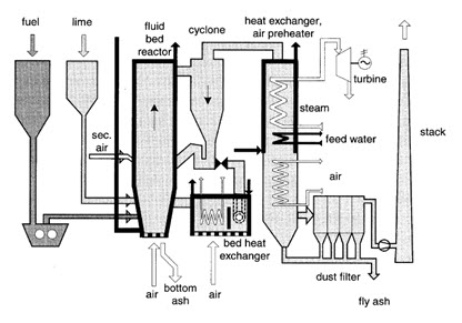
Special types offurnaces have been developed for straw that has verylow density and is usually stored in bales. Besideconventional grate furnaces operated with whole bales,cigar burners and other specific furnaces are in operation.Stationary or bubbling fluidized bed (SFB) as well ascirculating fluidized bed (CFB) boilers are applied forlarge-scale applications and often used for waste woodor mixtures of wood and industrial wastes, e.g., fromthe pulp and paper industry. In CFBboilers, nearly homogeneous conditions of temperatureand concentrations can be achieved, thus enabling highburnout quality at low excess air. The choice of differentbed materials in CFB offers additional opportunities ofcatalytic effects. Further, the option of heat removal from the bed allows controlling the combustion temperature and hence enables an operation at low excess air without excessive ash sintering. Since similar conditions for nitrogen conversion as by air and fuel staging are attained, relatively low NOX emissions are achieved.
Co-combustionOverview on Co-utilization.
A co-utilization of biomass with other fuels can be advantageous with regard to cost, efficiency, and emissions. Lower specific cost and higher efficiencies of large plants can be utilized for biomass and co-firing can reduce emissions of SOX and NOX. However, attention must be paid to increased deposit formation in the boiler and limitations in ash utilization due to constituents in biomass, especially alkali metals that may disable the use of ash in building materials. Due to undesired changes of ash compositions, the share of biomass is usually limited to approximately 10% of the fuel input. Hence, other opportunities are also of interest and the following three options for co-utilization of biomass with coal are applied:
(a) Co-combustion or direct co-firing: The biomass is directly fed to the boiler furnace (fluidized bed, grate, or pulverized combustion), if needed after physical preprocessing of the biomass such as drying, grinding, or metal removal.
(b) Indirect co-firing: The biomass is gasified and theproduct gas is fed to a boiler furnace (thus a combinationof gasification and combustion).
Parallel combustion:
The biomass is burnt in aseparate boiler for steam generation. The steam is usedin a power plant together with the main fuel.Co-combustion of biomass leads to a substitution offossil fuels and to a net reduction of CO2 emissions. Inmany countries co-firing is the most economic technologyto achieve the target of CO2 reduction and savings of CO2 taxes can therefore motivate biomass co-firing.
Co-combustion or Direct Co-firing withCoal
The main application nowadays is direct co-firingin coal-fired power stations. The typical size range isfrom 50 MW to 700 MW with a few units between 5and 50 MW. The majority of the plants are equippedwith pulverized coal boilers in which co-combustion canbe applied in different ways.
-
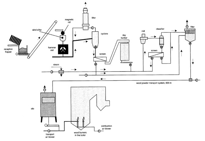
The biomass can be burnt in separate woodburners in the boiler. Due to the requirements ofpulverized combustion, drying, metal separation, andgrinding of the biomass is needed as pretreatment. Anexample is shown in a 635 MW power plant in theNetherlands that burns the majority of the local urban waste wood and demolition wood. Woodreplaces 3%-4% of the coal in this plant. Thanks to thescale and the flue gas cleaning, the urban waste woodis used with high efficiency and low environmentalimpact. At an electric efficiency of the plant of 43%, thenet efficiency for wood with regard to fuel pretreatmentis estimated at 36%-38%. As comparison: a modern 25MW wood-based fired plant reaches 30% efficiency.
-
As an alternative, the biomass can also be burnton a separate grate at the bottom of a pulverized coal boiler. The advantage is that costly andenergy-consuming fuel pretreatment is not needed, sincebiomass with high water content and large in size canbe burnt.
-
Further applications of co-combustion with coal arerelated to BFB, CFB, cyclone, and stoker boilers, whichaccept a much wider range of fuel size, composition, andmoisture content than burners in pulverized coal boilers.
Effects of Co-combustion on Plant Operationand Emissions
Co-firing can have severaleffects on the emissions and the plant operation: positiveeffects are that SOX and NOX emissions usuallydecrease due to the lower sulfur and nitrogen contentin biomass than in coal. Furthermore,alkali components in biomass ash can have aneffect of SOX removal. Since biomass has a high volatilecontent, it can also be used as reburn fuel for NOXreduction from the coal combustion, which gives afurther potential for significant decrease of the NOXemissions. Besides NO and NO2, also N2O can besignificantly reduced by co-firing of biomass in coal-firedfluidized bed boilers.
Negative effects of co-firing are additional investmentcost for biomass pretreatment and boiler retrofitting,higher operation cost due to increased fouling andcorrosion, and a possible decrease of the electric efficiency (if the superheater temperature has to bedecreased due to high temperature corrosion). Besidespotential poisoning of SCR catalyst also the efficiencyof electrostatic precipitators may be reduced. Furthermore,the utilization of the ash and the residues fromthe flue gas cleaning system (especially the De-SOXinstallation) has to be considered when co-firing biomass.The ash quality can be negatively influenced mainly by alkali metals and chlorine contained in biomass. Furthermore, also the content of unburnt carbon can increase. Usually a biomass input in the range of 5% to 10% according to the energy input is acceptable without major influence on the residues.
Other Applications of Co-combustion
Co-firing of biomass can also be applied in cement kilns, which is of special interest for contaminated waste wood. Additionally, biomass fuels can be co-fired in municipal solid waste (MSW) incinerators. This can be advantageous with respect to logistics and efficiency, since biomass can easily be stored while municipal waste needs to be burnt immediately. Further, the combination of biomass with oil or natural gas also offers specific advantages. Especially the topping with natural gas enables a significant increase of the plant efficiency, since steam from a biomass boiler can be superheated to higher temperatures with natural gas.
Indirect Co-firing and Parallel Combustion
Parallel combustion enables a complete separation of the ashes and flue gases from different fuels such as biomass and coal. Hence, no disadvantages or limitations result from undesired alkali metals or contaminants in the ash. Further, the flue gas cleaning equipment can be optimized for each fuel. Indirect co-firing of producer gas from biomass gasification also enables the separation of the ashes to a certain extent, while the flue gases cannot be separated. In comparison to parallel combustion, investment cost can be reduced because only one boiler and flue gas cleaning are needed.
Combustion and co-combustion of biomass
Last modified: Tuesday, 1 October 2013, 11:03 AM