Site pages
Current course
Participants
General
MODULE 1. Electro motive force, reluctance, laws o...
MODULE 2. Hysteresis and eddy current losses
MODULE 3. Transformer: principle of working, const...
MODULE 4. EMF equation, phase diagram on load, lea...
MODULE 5. Power and energy efficiency, open circui...
MODULE 6. Operation and performance of DC machine ...
MODULE 7. EMF and torque equations, armature react...
MODULE 8. DC motor characteristics, starting of sh...
MODULE 9. Polyphase systems, generation - three ph...
MODULE 10. Polyphase induction motor: construction...
LESSON 17. DC motor – Torque Equation
Torque Developed by a Motor. Figure 8. 4 (a) below shows a coil of a single turn, whose plane lies parallel to a magnetic field. Current flows into the paper in the left-hand side of the coil and out of the paper in the right-hand side of the coil. Therefore, the left-hand conductor tends to move downward with a force F1 and the right-hand conductor tends to move upward with a force
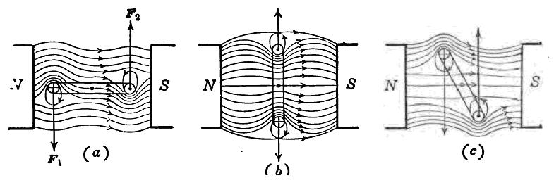
Fig. 8. 4 Torque developed at different positions of a coil.
F2.These two forces tend to rotate the coil about its axis. Both act to turn it in a counter-clockwise direction and so develop a torque. As the current in each of these conductors is the same and they lie in magnetic fields of the same strength, force F1 = F2. In Fig. 8. 4 (a) the coil is in the position of maximum torque because the perpendicular distance from the coil axis to the forces acting is a maximum. When the coil reaches the position Fig. 8. 4 (b) this is a position of zero torque because the perpendicular distance from the coil axis to the forces is zero. If, however, the current in the coil be reversed when the coil reaches position Fig. 8. 4 (b) and the coil be carried slightly beyond the dead center, as shown in Fig. 8. 4 (c) a torque is developed which tends to turn the coil in the counter-clockwise direction.
To develop a continuous torque in a motor, the current in each coil on the armature must be reversed just as it is passing through the neutral plane or plane of zero torque and a commutator is therefore necessary. This is analogous to using a commutator in connection with a generator in order that the current delivered to the external circuit may be uni-directional.
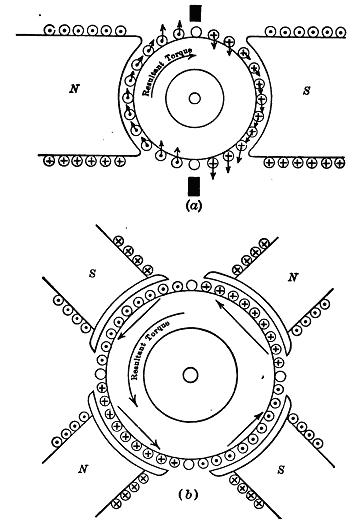
Fig. 8. 5 Torque developed by belt conductors in motor armatures
A single-coil motor as explained now would be impracticable as it has dead centers and the torque which it develops is pulsating. A two-coil armature would eliminate the dead centers, but the torque developed would still be more or less pulsating in character.
The best conditions are obtained when a large number of coils is used, just as in the armature of a generator. In fact there is no difference in the construction of a motor armature and a generator armature. In the figure 8. 5 (a), an armature and a field are shown for a 2-pole machine and the torque developed by each individual conductor is indicated. Figure 8. 5 (b) shows an armature and a field for a 4-pole machine. The direction of the torque developed by each belt of conductors is indicated by the arrow at that belt.
In armatures of this type a very small proportion of the total number of coils is undergoing commutation at any one instant. Therefore, the variation in the number of active conductors is so slight that the torque developed is substantially constant, for constant values of armature current and main flux.
The torque developed by any armature can be shown to be
T = K't ZIF
where K't = a constant of proportionality, involving the diameter of the armature, the parallel paths through the armature, the choice of units, etc.
Z = number of conductors on the surface of the armature.
I = current supplied to the armature, in A.
F = flux from one north pole entering the armature.
For any particular machine Z is a fixed quantity, so that the torque
T = Kt I F
where Kt is a new constant of proportionality, i.e., in a given motor, the torque is proportional to the armature current and to the strength of the magnetic field.
Example.- When a certain motor is drawing 50 A from the line it develops 60 Nm torque. If the field strength is reduced to 75 percent of its original value and the current increased to 80 A, what is the new value of the torque developed?
If the current remained constant the new value of torque, due to the weakening of the field, would be
0.75 × 60 = 45 Nm.
Due to the increase in the value of the current, however, the final value of torque will be
(80/50) × 45 = 72 Nm
Back Electromotive Force. The resistance of the armature of the ordinary 10-horsepower, 220-volt motor is about 0.05 ohm. If this armature were connected directly across 110-volt mains, the current, by Ohm's Law, would be 110/0.05 = 4400 A. This value of current is not only excessive but unreasonable, especially when we know that its rated current of that motor is 90 A. So when a motor is in operation, the current through the armature is evidently not determined by its ohmic resistance alone. The armature of a motor is in every way similar to that of a generator. The conductors on the armature surface are cutting flux and therefore must be generating an electromotive force. If the right-hand rule is applied to determine the direction of this induced electromotive force, it will be found that it is always in opposition to the current as shown below.
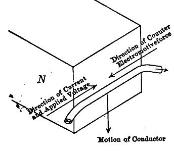
Fig. 8. 6 Torque developed by belt conductors in motor armatures
That is, it opposes the current entering the armature. This induced emf is called the back electromotive force or back emf. As the back emf opposes the current it must also oppose the line voltage. Therefore, the net emf acting in the armature circuit is the difference of the line voltage and the back electromotive force. Let V be the line voltage and E the back emf, then the net voltage acting in the armature circuit is V – E. The armature current follows Ohm's Law and is ![]() , where Ra is the armature resistance.
, where Ra is the armature resistance.
This equation may now be written as E = V - IaRa
In a generator, the induced emf (E) is equal to the terminal voltage (V) plus the armature resistance drop (IaRa). But here in a motor, the induced emf. is equal to the terminal voltage minus the armature resistance drop. The back emf must always be less than the terminal or impressed voltage if current is to flow in the armature.
Example.—Determine the back emf of a 10-hp motor, when the terminal voltage is 110 volts and its armature is taking 90 A. The armature resistance is 0.05 ohm.
E = 110 - (90 X 0.05) = 110 - 4.5 = 105.5 volts.
The equation developed earlier for induced electromotive force in a generator will obviously apply to a motor. That is, the back emf (induced emf in motor)
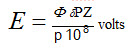
where j is the total flux entering the armature from one north pole, s the speed of the armature in revolutions per second, P the number of poles, Z the number of conductors on the surface of the armature, and p the parallel paths through the armature. As Z, P and p are all constants for any given motor, the back emf becomes
E = K1 φ S
where S being given in R. P. M.S
i.e. where ![]() K = 1/K1
K = 1/K1
“The speed of a motor is directly proportional to the counter electromotive force and inversely proportional to the field”
Substituting'for E, S = K (V - IaRa) / φ
Example.—A certain motor has an' armature resistance of 0.1 ohm. When connected across 110-volt mains and taking 20 amp. its speed is 1,200 r.p.m. What is its speed when taking 50 amp. from these same mains, with the field increased 10 per cent. ? .
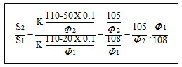
^S1 = 1200
Therefore, S2 = 1,200 (105 / 108) (φ1 / φ2)
But φ2 / φ1 = 1.10
Therefore, S2 = 1,060 r.p.m.
Last modified: Tuesday, 1 October 2013, 7:20 AM