Site pages
Current course
Participants
General
MODULE 1.
MODULE 2.
MODULE 3.
MODULE 4.
MODULE 5.
MODULE 6.
MODULE 7.
MODULE 8.
MODULE 9.
MODULE 10.
LESSON 19 BELTS
19.1 Introduction
To transmit power from the prime mover to the driven machine either flexible or non-flexible drive elements are used. Gears are an example of rigid or non-flexible drives whereas belts, chains and ropes are flexible drive elements. Flexible elements are used when there is larger centre distance between the shafts to be connected. Flexible drives are simple in construction, are less noisy, have low initial and maintenance cost and help in absorbing shock loads and damping vibrations. Low and variable velocity ratio is the main disadvantages of these drives.
19.2 Belt Drive
A belt drive consists of two pulleys attached to each shaft and an endless belt wrapped around them with some initial tension. Power is transmitted from the driver pulley to the belt and from the belt to the driven pulley with the help of friction. Friction between belt and pulley surface limits the maximum power that can be transmitted. If this limiting value is exceeded, belt starts slipping. Belts have limited life and should be periodically inspected for wear, aging, and loss of elasticity and should be replaced at the first sign of deterioration.

|
Figure 19.1 Flat and V-Belts |
Belts having rectangular cross-section are called flat belts and those with the trapezoidal cross-section are known as V-belts. Both the sections are shown in Figure 19.1.
Flat belts are used to transmit moderate amount of power between shafts less than 6m apart. V-belts are used along with pulleys having similar cross-section as that of the belt. These are used for higher power transmission between parallel shafts having smaller centre distance. Included angle in the groove of the pulley is kept smaller than the included angle of the belt cross-section. Due to this, bottom of the belt doesn’t touch the pulley and power is transmitted by friction between sides of the belt and inner walls of the pulley. This helps in larger amount of power transmission and lesser slip. To further increase the power transmission capacity, multiple V-belt system is used, in which power is transmitted from one shaft to the other with the help of more than one V-belts running on pulleys having multiple grooves.
Belts with circular cross-section or ropes are used to transmit large power between shafts more than 10m apart. Grooved pulleys called sheaves are used with the ropes. Rope fits in the groove, gripping its sides, reducing the chances of slip. Sheaves with multiple grooves are used to further increase the power transmission capacity. Pulleys used with flat belts are slightly crowned to keep the belt running centrally on the pulley. V-groove pulleys are used with V-belts, which have a groove deeper than the cross-section of belt so that bottom of the belt doesn’t touch the pulley. This leads to wedging action, due to which slip is lesser and it can transmit more power than a flat belt.
19.3 Types of Belt Drives
Commonly used belt arrangements are shown in Figure 19.2

|
Figure 19.2 Types of Belt Drives
|
These different arrangements are used depending upon the required direction of rotation of driven shaft, plane of rotation of the driving and driven shafts and the angle between the axes of shafts. When the direction of rotation of driver and driven pulleys is required to be the same open-belt drive is used. If the driven pulley is to be rotated in the opposite direction to that of the driving pulley, cross-belt drive is used. Due to larger angle of contact between the belt and the pulley, cross-belt drive can transmit more power than an open-belt drive but the wear rate is higher for cross-belt drive as the belt bends in two different planes. For the shafts arranged at right angles, quarter turn belt drive is used. Idler pulleys are used to increase the angle of contact, obtain higher velocity ratio and increase the belt tension. Belt is subjected to reversed bending when idler pulley is used which may reduce the life of the belt.
19.4 Belt Material
The belt material should have high coefficient of friction, tensile strength, wear resistance and flexibility and low flexural rigidity. Commonly used belt materials are:
Leather: The most widely used material for belts is oak-tanned and chrome-tanned leather. Leather belts are available in two varieties-oak tanned and chrome tanned. Oak-tanned leather is used for ordinary applications and chrome-tanned is used for applications where belts are exposed to moisture, oil or chemicals. Leather strips are cemented together to increase thickness and life of the belt. Belts are specified according to the number of layers (called plies) e.g. single, double or triple ply belts.
Rubber: Cotton duck or canvas impregnated with rubber is also used as belt material. Cotton duck or canvas provides strength whereas the rubber provides protection and increases coefficient of friction. These are generally available in three to ten plies. They should be vulcanized if they are to be exposed to high temperature, oil or grease; otherwise they get damaged very quickly. Service life of rubber belts is shorter than that of leather belts but these are cheaper.
Balata: These belts are similar to rubber belts except that cotton duck impregnated with balata gum instead of rubber. These belts are acid and water proof and also don’t get affected by animal oils and alkalis but get seriously affected by the mineral oils. Balata belts have 20-40% higher strength than the rubber belts. Balata starts softening and becomes sticky at temperatures above 40°C. So these are not recommended for high temperature applications.
Cotton or Fabric: Fabric belts are made from a number of closely woven layers of cotton or canvas ducks. To make the belt waterproof, they are impregnated with linseed oil. Cotton belts are cheaper and are suitable for warm and damp conditions and require less attention. These are generally used in farm machinery; conveyors etc. Mechanical properties of fabric belts are at par with rubber belts.
Plastics: Plastic belts have plastic core of nylon canvas or thin plastic sheets surrounded by a layer of rubber. Plastic-cored belts have high strength almost twice of that of leather belts. These can be wrapped around very small pulleys and can be operated at high speeds.
19.5 Velocity Ratio
Velocity Ratio is the ratio of speeds of driver and driven pulley. Let
N1, d1 = speed (rpm) and diameter of driving pulley
N2, d2 = speed (rpm) and diameter of driven pulley
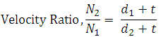
t = thickness of belt
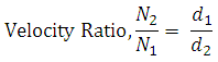
If thickness of the belt is considered,
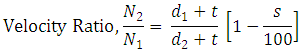
Slip of belt over the pulleys reduces the velocity ratio. Let
s1 = percentage slip between driver and belt
s2 = percentage slip between belt & driven pulley
s = total percentage slip
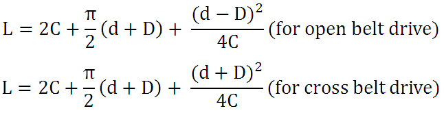
19.6 Length of the Belt
If d & D are diameters of smaller and larger pulleys respectively with C as the centre distance between the axes of the pulleys, length of the belt is given by,
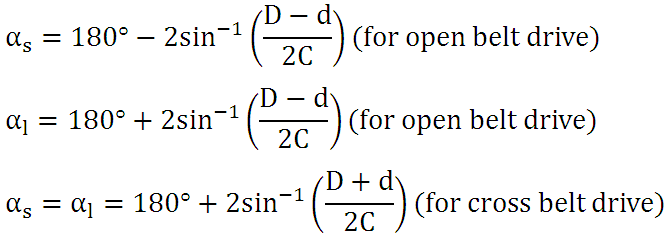
19.7 Angle of Wrap
Angle of wrap on smaller (as) and larger pulleys (al) are given by,
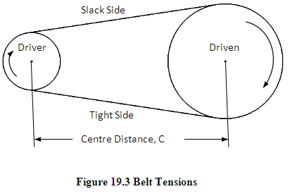
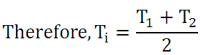
19.8 Belt Tension
To increase friction and avoid slip, some initial tension is provided in the belt. Even when the belt is not transmitting any power, there is some initial tension (Ti ) in it, provided to avoid slipping of the belt. Consider a flat belt drive shown in figure 19.3, with the smaller pulley as driver and the larger pulley as driven. When the driver starts rotating (say clockwise), it applies a tangential force on the belt and tends to rotate it. This leads to increase in tension on one side and decrease in tension on the other side of the belt by same amount, dT, which equals the tangential force applied by the pulley. Side of the belt in which the tension increases is called tight side (lower side in this case) and the side in which tension decreases is called slack side.
Tension in tight side, T1 = Ti + dT
Tension in slack side, T2 = Ti - dT
Ratio of tension in tight side and slack side is given by,
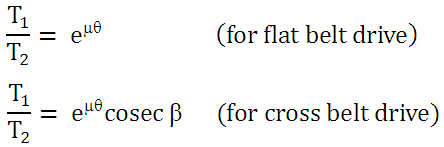
Where, μ = coefficient of friction between belt & pulley
Θ = angle of contact
β = half of the groove angle of v-belt
When the belt operates at higher speeds, centrifugal force acts on it, which increases the tension in the belt. This additional tension in the belt due to the centrifugal force is called centrifugal tension and it can be proved that, centrifugal tension,
Tc = mv2
where, m = mass of the belt per unit length
v = velocity of the belt in m/s
Therefore the tensions in the tight and slack side increase by an amount equal to Tc. The maximum tension in the belt then becomes,
T = T1 + TC
If b and t are width & thickness of a flat belt and [σ] is the maximum allowable stress in the belt, maximum permissible tension for it can be given by,
![]()
For belt to run safely, maximum tension in the belt should not cross the permissible limit i.e.
19.9 Power Transmitted by Belt Drive
Power transmitted by the belt is given by, ![]()
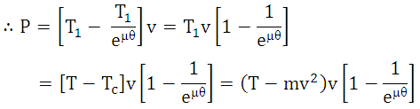
To obtain the condition for maximum power transmission,
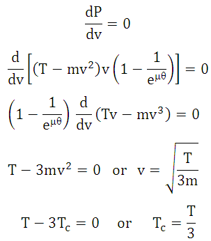
To calculate the limiting values T and [T] can be equated. Therefore, for maximum transmission of power, centrifugal tension in the belt should be 1/3rd of the maximum permissible tension in the belt or velocity of the belt should be 
References
-
Design of Machine Elements by VB Bhandari
-
Fundamentals of Machine Component Design by R.C. Juvinall & K.M. Marshek
-
Mechanical Engineering Design by J.E. Shigley
-
Analysis and Design of Machine Elements by V.K. Jadon
-
Design of Machine Elements by C.S. Sharma & K. Purohit
-
Machine Design by R.S. Khurmi
Last modified: Friday, 21 March 2014, 5:30 AM