Site pages
Current course
Participants
General
MODULE 1.
MODULE 2.
MODULE 3.
MODULE 4.
MODULE 5.
MODULE 6.
MODULE 7.
MODULE 8.
MODULE 9.
MODULE 10.
LESSON 21 FLAT BELT PULLEYS
21.1 Introduction
Pulleys are the wheels used to transmit power from one shaft to another, with the help of belts. Proper selection of diameters of pulleys is important as the velocity ratio is the inverse ratio of the diameters of driving and driven pulleys. For the belt to travel in a line normal to the pulley faces, the pulleys must be perfectly aligned with each other. Pulleys should have following important properties:
- Ability to absorb shocks
- High heat conductivity
- High corrosion resistance
- High coefficient of friction to reduce belt slippage
- High strength to weight ratio
Pulley has three main components: i. Hub ii. Arms/spokes or web iii. Rim
21.1 Pulley Material
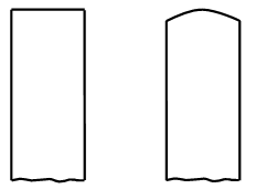
Pulleys are generally made of cast iron, forged steel, wood or compressed paper pulp. Because of their low cost, cast iron pulleys are most widely used. Arms or spokes of cast iron pulleys have elliptical cross-section and can have straight or curved shape as shown in figure 21.1a. In some pulleys, instead of arms, web is provided to join hub with rim, as shown in figure 21.1 b. Split cast iron pulleys, shown in figure 21.2, are made in two halves that are bolted together. These are easier to mount on shafts with a range of diameters, by tightening those on the shaft.


a. Pulleys with Arms


b. Pulley with Web
Figure 21.1 Solid Cast Iron Pulleys
Steel pulleys have higher strength, are lighter in weight and can run at higher speeds. But they have lower coefficient of friction in comparison to cast iron pulleys. Steel pulleys are generally made in two parts, which are bolted together on the shaft. Bushings are provided to take care of shafts of different diameters and for normal service; power is transmitted without key, only through frictional force obtained by clamping.

Figure 21.2 Split Cast Iron Pulley
Wooden pulleys are lighter and have higher coefficient of friction. Wooden pulleys are made of segments glued together under heavy pressure. Protective coatings of shellac or varnish are applied to avoid warping due to moisture. Wooden pulleys are also made as solid or split and have cast iron hubs with keyways. Adjustable bushings are also used in some of the wooden pulleys.
Paper pulleys are generally used for smaller centre distances to transmit power from electric motors. These are made from compressed paper fibre and are formed with a metal in the centre.
21.3 Crowning of Pulleys
a. Flat Pulley b. Crowned Pulley
Figure 21.3 Crowning of Pulleys
In case of flat belts, thickness of the rim is increased from the centre so that it gets convex shape as shown in figure 21.3. This is known as crowning of the pulley. It helps in preventing the belt from running off the pulley by bringing it to the mid-plane of pulley whenever it moves to sides. Thus it helps in keeping the belt running in equilibrium position near the centre of the rim.
21.4 Design of Cast Iron Pulleys
The following procedure may be adopted for the design of cast iron pulleys.
21.4.1 Dimensions of Pulley
Diameter of the pulley (D) is selected depending upon the required velocity ratio, as discussed in the selection of belts.
Width of the pulley or face of the pulley (B) is taken 1.25 times the width of belt (b).
B = 1.25 b
Thickness of the pulley rim (t) is taken between (D/300 +2)mm and (D/300 +3)mm for single belt and for double belt.
21.4.2 Dimensions of Arms
Number of arms can be taken as follows:
Pulley Diameter No. of Arms
< 200 mm Web (with thickness = rim thickness)
> 200mm and < 450mm 4
> 500 mm 6
Cross-section of arms is generally elliptical with major axis (b1) equal to twice the minor axis (a1). The cross-section of the arm is obtained by considering the arm as cantilever, fixed at the hub end and carrying a concentrated load at the rim end and having a length equal to the radius of the pulley. Also, it is assumed that at any given time, the power is transmitted from the hub to the rim or vice versa, through only half of the total number of arms.
Tangential load per arm is given by, 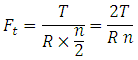
where, T = Torque transmitted
R = Radius of pulley
n = Number of arms
Maximum bending moment on the arm at the hub end,
Maximum bending stress is given by,
![]()
where, I = Moment of inertia of cross-sectional area of the arm about the axis of rotation
= ![]() as b1 = 2a1
as b1 = 2a1
y = Distance from neutral axis to the outer most fibre = b1 / 2 = a1
So, required dimensions of the arm, near the hub, can be determined from above relation for a known value of allowable tensile stress, [ ]. A taper, generally of 1/48 to 1/32, is provided on the arms, from hub to rim.
21.4.3 Dimensions of Hub
For known shaft diameter (d), diameter of the hub (d1) can be taken as:
![]()
But the diameter of the hub should not be greater than 2d.
Length of the hub can be taken as,
![]()
The minimum length of the hub is 2/3rd of the width of the pulley and it should not be more than the width of the pulley.
References
-
Design of Machine Elements by VB Bhandari
-
Fundamentals of Machine Component Design by R.C. Juvinall & K.M. Marshek
-
Mechanical Engineering Design by J.E. Shigley
-
Analysis and Design of Machine Elements by V.K. Jadon
-
Design of Machine Elements by C.S. Sharma & K. Purohit
-
Machine Design by R.S. Khurmi
Last modified: Friday, 21 March 2014, 8:51 AM