Site pages
Current course
Participants
General
MODULE 1.
MODULE 2.
MODULE 3.
MODULE 4.
MODULE 5.
MODULE 6.
MODULE 7.
MODULE 8.
MODULE 9.
MODULE 10.
LESSON 20 SELECTION OF BELTS
20.1 Selection of Flat Belt
In most of the applications, belts are generally selected by the designer from the manufacturer’s catalogue. This helps in the use of standard available sizes. Following input data is required for the selection of belt:
- Power to be transmitted
- Transmission ratio
- Centre distance
Following is the procedure for selection of a flat belt:
1. Select suitable belt material
Two types of belts are generally available – HI-SPEED duck belting and FORT duck belting. Specified transmission capacities of these two types, for an angle of contact of 180°and belt velocity of 5.08 m/s, is as follows:
Type of Belt Transmission Capacity/ Power Rating (R)
HI-SPEED 0.012 kW / mm width / ply
FORT 0.015 kW / mm width / ply
2. Assume belt velocity and calculate diameters of pulleys
Optimum value of belt velocity lies between 15 m/s to 25 m/s. Assume any value for belt velocity, within this range and calculate diameter of the smaller (driving) pulley using the following relationship:

where, v = velocity of belt
N1 = input speed (rpm) of smaller pulley
Diameter of larger pulley (D) can be calculated, for required velocity ratio i.e. for required output speed (N2), using the following relationship:
N1d = N2D
3. Calculate design power
For design purpose, maximum power transmitted by the belt is obtained by multiplying the required power (P) by a load correction factor (Kload). Value of Kload can be taken from Table 20.1. Also, Power transmission capacity of belts (Step 1) is based on angle of contact of 180°. But in actual conditions, angle of contact varies depending upon diameters of pulleys and centre distance. If angle of contact is less than 180°, there is additional tension in the belt. This is taken care of, by multiplying the required power to be transmitted by angle of contact factor, Ka.. Value of Ka can be taken from Table 20.2. Design power of the belt is thus given by,
![]()
Table 20.1 Load Correction Factor, Kload
|
Type of Load |
Kload |
|
|
Normal Load |
|
1.0 |
|
Steady Load |
(light machine tools, fans, centrifugal pumps, conveyors etc.) |
1.2 |
|
Intermittent Load |
(compressors, blowers, heavy-duty fans, line shafts, reciprocating pumps, heavy-duty machines etc.) |
1.3 |
|
Shock Load |
(hammers, grinders, rolling mills, vacuum pumps etc.) |
1.5 |
Table 20.2 Angle of Contact Factor, Ka
|
Angle of Contact (as) |
120° |
130° |
140° |
150° |
160° |
170° |
180° |
190° |
200° |
210° |
|
Angle of Contact Factor, Ka |
1.33 |
1.26 |
1.19 |
1.13 |
1.08 |
1.04 |
1.00 |
0.97 |
0.94 |
0.91 |
4. Determine corrected power rating
Power transmission capacity of belts (Step 1) is based on belt velocity of 5.08 m/s. But in actual conditions, belts run at different speeds. For different velocity, corrected power rating is obtained as follows:
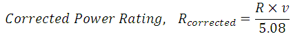
where, R is Power Transmission Capacity or Rating of belt and v is actual belt velocity.
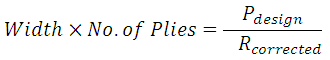
5. Calculate the product of width and number of plies by dividing maximum power to be transmitted by corrected power rating.
6. Select suitable width and number of plies
Suitable width and number of plies can now be selected from the catalogue so that the desired product is obtained. Table 20.3 gives standard width thickness and number of plies for rubber belts.
Table 20.3 Rubber Belt Data
|
No. of Plies |
Thickness (mm) |
Belt Width (mm) |
|
3 |
3.9 |
25, 32, 40, 50, 63, 71 |
|
4 |
5.2 |
40, 50, 63, 71, 80, 90, 100, 112, 125, 140 |
|
5 |
6.5 |
71, 80, 90, 100, 112, 125, 140, 160 |
|
6 |
7.8 |
112, 125, 140, 160, 180, 200, 224, 250 |
|
7 |
9.1 |
160, 180, 200, 224, 250, 280, 315 |
|
8 |
10.4 |
224, 250, 280, 315, 355, 400, 450, 500 |
7. Calculate desired length of belt and specify all the dimensions.
20.2 Selection of V-Belts
V-belts are also selected from the manufacturer’s catalogue. Following is the procedure for selection of a flat belt:
1. Select suitable V-belt section
Five types of standard V-belt sections are available. Dimensions of these are given in Table 20.4. Refer figure 20.1 for basic dimensions of the trapezoidal section of V-belt.
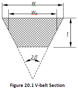
Table 20.4 Dimensions of V-belt Sections
|
Section |
A |
B |
C |
D |
E |
|
Pitch Width, wp (mm) |
11 |
14 |
19 |
27 |
32 |
|
Nominal Top Width, w (mm) |
13 |
17 |
22 |
32 |
38 |
|
Nominal Thickness, t (mm) |
8 |
11 |
14 |
19 |
23 |
|
Recommended Velocity (m/s) |
25 |
25 |
25 |
30 |
30 |
|
Recommended Power Range (kW) |
0.4 - 4.0 |
1.5 - 15 |
10 - 70 |
35 - 150 |
70 – 260 |
|
Recommended Minimum Pitch Diameter of Pulley (mm) |
125 |
200 |
315 |
500 |
630 |
2. Determine diameters of pulleys
Recommended diameter of smaller pulley (d) can be taken from table 20.4 for selected cross-section. Diameter of larger pulley (D) can be calculated, for required velocity ratio i.e. for given input speed (N1) and required output speed (N2), using the following relationship:
N1d = N2D
3. Calculate design power
For design purpose, maximum power transmitted by the belt is obtained by multiplying the required power (P) by service factor (Ks). Value of Ks can be taken between 1 and 2, depending upon the service conditions i.e. light, medium, heavy or extra-heavy duty, type of driver and driven machinery and operational hours.
Pdesign = Ks X P
4. Determine Pitch Length and Centre Distance
Calculate length of the belt from its relation with d, D and C. Select the nearest standard value of belt pitch length from table 20.5. Calculate exact centre distance, C from the relation again.
Table 20.5 Belt Pitch Lengths & Pitch Length Correction Factor
|
Belt Pitch Length (mm) |
Pitch Length Correction Factor, Klength |
||||
|
Belt Cross-section |
|||||
|
A |
B |
C |
D |
E |
|
|
630 |
|
|
|
|
0.80 |
|
|
930 |
|
|
|
0.81 |
|
700 |
|
1560 |
2740 |
|
0.82 |
|
|
1000 |
|
|
|
0.83 |
|
790 |
|
1760 |
|
|
0.84 |
|
|
1100 |
|
|
|
0.85 |
|
890 |
|
|
3130 |
|
0.86 |
|
|
1210 |
1950 |
3330 |
|
0.87 |
|
990 |
|
|
|
|
0.88 |
|
1100 |
1370 |
2190 |
3730 |
4660 |
0.90 |
|
|
|
2340 |
|
|
0.91 |
|
|
1560 |
2490 |
4080 |
5040 |
0.92 |
|
1250 |
|
|
|
|
0.93 |
|
|
|
2720 |
4620 |
5420 |
0.94 |
|
|
1760 |
2800 |
|
|
0.95 |
|
1430 |
|
3080 |
|
6100 |
0.96 |
|
|
1950 |
|
5400 |
|
0.97 |
|
1550 |
|
3310 |
|
|
0.98 |
|
1640 |
2180 |
3520 |
|
6850 |
0.99 |
|
1750 |
2300 |
|
6100 |
|
1.00 |
|
1940 |
2500 |
4060 |
|
7650 |
1.02 |
|
|
|
|
6840 |
|
1.03 |
|
2050 |
2700 |
|
|
|
1.04 |
|
2200 |
2850 |
4600 |
7620 |
9150 |
1.05 |
|
2300 |
|
|
|
|
1.06 |
|
|
|
|
8410 |
9950 |
1.07 |
|
2480 |
3200 |
5380 |
|
|
1.08 |
|
2570 |
|
|
9140 |
10710 |
1.09 |
|
2700 |
3600 |
|
|
|
1.10 |
|
|
|
6100 |
|
|
1.11 |
|
2910 |
|
|
10700 |
12230 |
1.12 |
|
3080 |
4060 |
|
|
|
1.13 |
|
3290 |
|
6860 |
|
13750 |
1.14 |
|
|
4430 |
|
|
|
1.15 |
|
3540 |
4820 |
7600 |
12200 |
|
1.16 |
|
|
5000 |
|
13700 |
15280 |
1.17 |
|
|
5370 |
|
|
|
1.18 |
|
|
6070 |
|
15200 |
16800 |
1.19 |
|
|
|
9100 |
|
|
1.20 |
|
|
|
10700 |
|
|
1.21 |
Table 20.6 Angle of Contact Factor, Ka
|
Angle of Contact on Smaller Pulley, as |
Angle of Contact Factor, Ka |
|
|
0.00 |
180 |
1.00 |
|
0.05 |
177 |
0.99 |
|
0.10 |
174 |
0.99 |
|
0.15 |
171 |
0.98 |
|
0.20 |
169 |
0.97 |
|
0.25 |
166 |
0.97 |
|
0.30 |
163 |
0.96 |
|
0.35 |
160 |
0.95 |
|
0.40 |
157 |
0.94 |
|
0.45 |
154 |
0.93 |
|
0.50 |
151 |
0.93 |
|
0.55 |
148 |
0.92 |
|
0.60 |
145 |
0.91 |
|
0.65 |
142 |
0.90 |
|
0.70 |
139 |
0.89 |
|
0.75 |
136 |
0.88 |
|
0.80 |
133 |
0.87 |
|
0.85 |
130 |
0.86 |
|
0.90 |
127 |
0.85 |
|
0.95 |
123 |
0.83 |
|
1.00 |
120 |
0.82 |
5. Determine corrected power rating
Power transmission capacity / rating (R) for a single V-belt, for different types of cross-sections, can be taken from manufacturer’s catalogue. Corrected power rating is obtained by multiplying the power rating by Pitch Length Correction Factor (Klength) and Angle of Contact Factor, Ka as follows:
![]()
Values of Klength and Ka can be taken from table 20.5 and table 20.6 respectively.
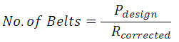
6. Determine the number of belts required
Required number of belts is determined by dividing the design power with corrected power rating for one belt.
References
-
Design of Machine Elements by VB Bhandari
-
Fundamentals of Machine Component Design by R.C. Juvinall & K.M. Marshek
-
Mechanical Engineering Design by J.E. Shigley
-
Analysis and Design of Machine Elements by V.K. Jadon
-
Design of Machine Elements by C.S. Sharma & K. Purohit
-
Machine Design by R.S. Khurmi
Last modified: Friday, 21 March 2014, 7:30 AM