


Site pages
Current course
Participants
General
MODULE 1.
MODULE 2.
MODULE 3.
MODULE 4.
MODULE 5.
MODULE 6.
MODULE 7.
MODULE 8.
MODULE 9.
MODULE 10.
LESSON 29 DESIGN OF LEVERS
29.1 Introduction
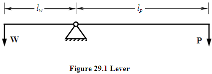
Lever is a simple mechanical device, in the form of a straight or curved link or a rigid rod, pivoted about the fulcrum. It works on the principle of moments and is used to get mechanical advantage and sometimes to facilitate the application of force in a desired direction. Examples of levers are: straight tommy bar used to operate screw jack, bell crank lever, rocker arm, lever of lever loaded safety valve etc. Figure 29.1 shows the construction of a simple lever. P is the applied effort required to overcome load, W.
Ratio of load to effort is called Mechanical Advantage and ratio of effort arm length to load arm length is called leverage.
29.2 Classes of Levers
Depending upon the position of load point, effort point and fulcrum, levers are classified into following classes:
|
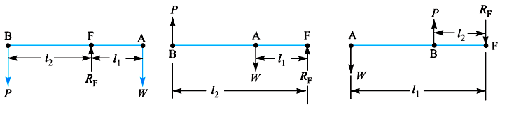
Class I Levers |
Lever having the fulcrum located between the load point and effort point is called Class I lever. Examples are rocker arm, bell crank lever etc. Mechanical advantage of such levers is greater than one as effort arm is larger than the load arm. |
|
Class II Levers |
Lever having load point located between the fulcrum and effort point is called Class II lever. Lever used in safety valve is an example of lever of this class. The effort arm is larger than the load arm; therefore the mechanical advantage is more than one. |
|
Class III Levers |
Lever having effort point located between the fulcrum and load point is called Class III lever. The effort arm, in this case, is smaller than the load arm; therefore the mechanical advantage is less than one. Due to this, the use of such type of levers is not recommended. However a pair of tongs, the treadle of a sewing machine etc. are examples of this type of lever. |
|
Figure 29.2 Class I, Class II and Class III Lever |
29.3 Design of Lever
Design of lever involves determination of various dimensions of the lever for a specified load or output force required. For a specified load or output force desired, effort required can be calculated using principle of moments. Due to these forces, arms of the lever are subjected to bending and are designed based on that. Reaction force acting on the fulcrum can be calculated. Fulcrum of the lever is a pin joint and is designed based on bending and bearing considerations. Design procedure is discussed below.
29.3.1 Determination of Forces
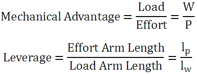
If the load and effort are parallel to each other, as shown in figure 29.2, reaction on the fulcrum is the algebraic sum of these two forces. But if the load and effort are inclined to each other at an angle q, as shown in figure 29.3, reaction (R) at the fulcrum can be determined as:
|
Figure 29.3 Angled Lever |
29.3.2 Design of Lever Arms
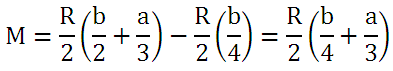
Arms are subjected to bending moment and their section is estimated from bending stress consideration. Figure 29.4 shows lever with fulcrum located between the load and the effort point. Bending moment is zero at the point of application of forces and is maximum at the fulcrum. Maximum Bending Moment is given by,
|
Figure 29.3 Lever Arms |
Maximum Bending Stress is then given by, M = Plp
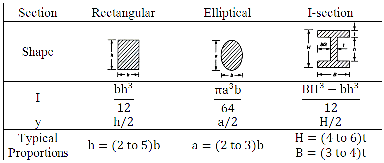
Most commonly used sections for lever arms are: rectangular, elliptical and I-section. Values of moment of inertia, I and distance of farthest fibre from neutral axis, y for these sections are given in table 29.1.
Table 29.1 Common Sections used for Lever Arms
|
Figure 29.4 Section of Lever Arm at Fulcrum |
Therefore using suitable values of I and y for selected section, its dimensions can be finalised so that the bending stress remains within the allowable limits. Often the arms are made with cross-section reducing from central portion to the point of application of load. This is done to save material using uniform strength condition. Critical section of the lever (section of maximum bending moment) becomes weak due to hole made for pin. To compensate for the reduced strength, width of that section is increased or boss is provided as shown in figure 29.4.
29.3.3 Design of Fulcrum
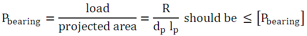
Fulcrum of lever is a pin joint as shown in figure 29.5. Pin is designed based on bearing and bending considerations as discussed below.

Figure 29.5 Lever Fulcrum
Bearing Failure
The permissible bearing pressure ([Pbearing]) depends upon relative velocity, frequency of relative motion and the lubrication condition between the pin and the bush. The usual range of allowable bearing pressure for brass/bronze bush and steel pin is 10-25 N/mm2. Lower values are used for high relative velocity, frequent motion and intermittent lubrication conditions. If dp and lp are diameter and length of the pin respectively, bearing pressure is given by,
Shear Failure
Pin is subjected to double shear and maximum shear stress is given by, 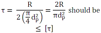
|
|
Bending Failure
As discussed in the design of pin for knuckle joint, when the pin is loose in the eye, which is a desired condition here for relative motion, pin is subjected to bending moment. It is assumed that: Load acting on the pin is uniformly distributed in the eye and uniformly varying in the two parts of the fork. Maximum Bending Moment (at centre) is given by,
Maximum Bending Stress in the pin, 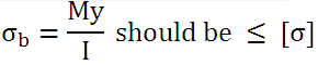
where, 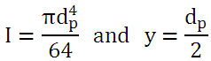
29.4 Lever Material & Factor of Safety
Levers are generally forged or cast. It is difficult to forge curved levers with complicated cross-sections and have to be cast. As the levers are subjected to tensile stress due to bending, cast iron is not recommended to be used as material for levers. Aluminium alloys are generally used for levers. For severe loading and corrosive conditions, alloy steels are used. Suitable heat treatment processes are also often employed to improve wear and shock resistance of lever. Factor of safety of 2 to 3 on yield strength is generally used. For severe loading conditions or fatigue loading higher factor of safety is also taken.
References
- Design of Machine Elements by VB Bhandari
- Analysis and Design of Machine Elements by V.K. Jadon
- Design of Machine Elements by C.S. Sharma & K. Purohit
- Machine Design by P.C. Sharma & D.K. Aggarwal
- Machine Design by R.S. Khurmi
Last modified: Monday, 24 March 2014, 11:34 AM