Site pages
Current course
Participants
General
MODULE 1.
MODULE 2.
MODULE 3.
MODULE 4.
MODULE 5.
MODULE 6.
MODULE 7.
MODULE 8.
MODULE 9.
MODULE 10.
LESSON 30 DESIGN OF COLUMNS
30.1 Introduction
A slender machine component, having considerable length in comparison to its cross-sectional dimensions, subjected to a compressive load is known as column, strut, pillar or stanchion. Examples of columns are push rods of valve mechanisms, piston rods in hydraulic / pneumatic cylinders, connecting rods, power screws etc.
If a machine member with comparable length and cross-sectional dimensions is subjected to axial compressive load as shown in figure 30.1a, compressive stresses are developed and it deforms according to Hook’s law. Failure occurs when the compressive stress reaches the yield strength. But when a machine member, having considerably larger length than cross-sectional dimensions, is subjected to compressive load as shown in figure 30.1b, it may fail due to buckling. Buckling is sudden large lateral deflection, which occurs when the compressive load reaches certain limit called critical load (Wcritical). It is different from lateral deflection of a beam. Lateral deflection of beam increases gradually with increase in lateral load. On the other hand, in case of buckling, there is no load in the lateral direction and there is no lateral deflection also before the axial compressive load reaches the critical load. Once the load reaches critical load, sudden lateral deflection takes place resulting in collapse of the column. Thus buckling leads to sudden and total failure that takes place without any warning.
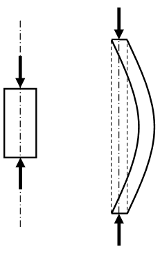
(a) (b)
Figure 30.1 Machine Members subjected to Compressive Load
30.2 Slenderness Ratio
Slenderness ratio is an important parameter that affects the critical load. It is defined as the ratio of length of the column to least radius of gyration of the cross-section about its axis.
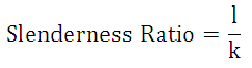
where, l = length of the column
k = radius of gyration of the cross-section about its axis = 
where, A = Area of Cross-section
I = Least Moment of Inertia of the Cross-section
Buckling does not take place if the slenderness ratio is less than 30 and such members are designed on the basis of compressive stresses only. But if the slenderness ratio is more than 30, buckling takes place at critical load and critical load becomes the design criteria.
30.3 Critical Load Prediction
Various scientists have developed different relations for the prediction of critical load, out of which only two basic relations are discussed here. For the column too be safe in buckling, maximum load to which the column is subjected, must be less than the critical load.
30.3.1 Euler’s Equation
According to Euler, buckling takes place when the compressive load reaches following critical value.
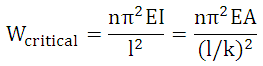
where, E = Modulus of Elasticity of Column Material
n = End Fixity
= 4 (both ends fixed)
= 2 (one end fixed and other end hinged)
= 1 (both ends hinged)
= 0.25 (one end fixed and other end free)
30.3.2 Johnson’s Equation
According to Johnson, critical load is given by,
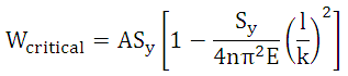
where, Sy = Yield Strength of Screw Material
References
-
Design of Machine Elements by VB Bhandari
-
Analysis and Design of Machine Elements by V.K. Jadon
-
Design of Machine Elements by C.S. Sharma & K. Purohit
-
Machine Design by P.C. Sharma & D.K. Aggarwal
-
Machine Design by R.S. Khurmi
Last modified: Tuesday, 25 March 2014, 4:16 AM