Site pages
Current course
Participants
General
Module 1. Hydraulic Basics
Module 2. Hydraulic Systems
MODULE 3.
MODULE 4.
MODULE 5.
MODULE 6.
MODULE 7.
MODULE 8.
LESSON 17. Hydraulic Circuit Fittings and Connectors
17.1 Introduction
A hydraulic system includes various components like reservoir, pump, actuator, motor, accumulator, valves, intensifier etc. These components are connected with each other in different configurations to form different tasks. The connections are made with the help of fittings and connectors. Thus fittings and connectors are of great importance for the functioning of hydraulic system components. There are different types ofconnectors available, which dependon the type of circulatory system (pipe, tubing, or flexible hose), fluid medium, operating pressure of a system etc. Some of thecommonly used fittings and connectors arediscussed as under.
17.2 Threaded Connectors
Thesetype of connectors are generally used in low-pressure hydraulic systems. These are normally made of steel, copper, or brass, with varying designs. The connectors are made with standard female threading cut onthe inside surface. The end of the pipe is threaded with outside (male) threads for connecting.Standard pipe threads are tapered slightlyto ensure tight connections. A straight threaded connector is shown in Fig. 17.1. O-ring seal is provided for leak proof connection.
Fig. 17.1: A Threaded Connector
Add Sktch
17.3 Flared Connectors
Flared connectors provide safe, strong and dependable connections and this method does not require any thread, weld, or solder in the tubing. A connector consists of a fitting, a sleeve, and a nut. Fittings are made of steel, aluminum alloy, or bronze. The fittings should be of a material that is similar to that of a sleeve, nut, and tubing. Tubing used with flared connectors must be flared before being assembled. A tube with flared end is shown in Fig. 17.2 (a). A nut fits over a sleeve and, when tightened, draws the sleeve and tubing flare tightly against a male fitting to form a seal as shown in Fig. 17.2 (b). A male fitting has a cone-shaped surface with the same angle as theinside of a flare. The tubes are normally flared at 37° from the centreline. In some of the applications this angle may also be 45°.Thesetype of fittings are comparatively less expensive. Flared connectors will have leak if the flare is distorted, split and eccentric or if the sleeve is damaged.
(a) (b)
Fig. 17.2: (a) A Tube with Flared End (b) A Flared Joint
Add sktch
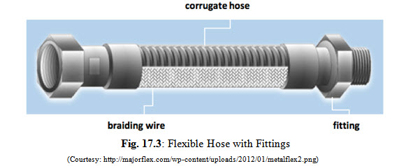
17.4 Flexible Hose Couplings
Flexible pipes are generally used to prevent vibration transmission or to allow relative movement between the ends. Hydraulic pumps are usually connected to the system with a flexible hose to prevent transmission of vibrations. The flexible tubes are made up of nylon or polyurethane but rubber tubes may also be utilized. Flexible hosing consists of several concentric layers. The material of the inner tubing is compatible with the hydraulic oil and its operating temperature. One or more braided reinforcing layers cover the inner tubing. The outer layer is provided to resist abrasion and protect inner layers from physical damage. Flexible hose coupling fittings are an integral part of hose assembly. A flexible hose with integral fittings is shown in Fig. 17.3.
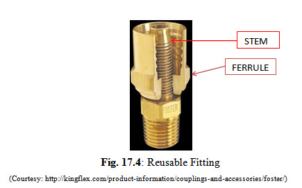
17.5 Reusable Fittings
Reusable couplings are attached to a hose using a ferrule. A ferrule is a collar which is screwed on to the hose cover. The stem is wedged into the tube of the hose using threads on the ferrule. The compression of the hose between the stem and the ferrule holds the coupling on the hose. A reusable coupling with sectioned view of the ferrule is shown in Fig. 17.4.Permanent couplings are attached to the hose using a crimping tool. As the coupling is crimped inward, serrations on the ferrule pierce the hose cover.
17.6 Bite Ring Type Compression Fittings
Sometimes thickness of the tube is more and it becomes difficult to flare it. In such situations flare less fittings are used. Bite ring compression fittings consist of a bite ring or a ferrule having sharp leading edge which is pressed against the tube tightening the nut as shown in Fig. 17.5. The wedging action of the bite ring makes a seal between the tube and connector body.
Fig. 17.5: Bite Ring Compression Fitting
Add sktch
17.7 Leakage
Hydraulic system may havesome amount of leakage, which reducesefficiency of the system and results in power loss.Leakageis not always due to faults, sometimes leakage is introduced deliberately in a planned manner. The leakage may be internal, external, or both.
17.7.1 Internal Leakage
This type of leakage is generally provided or built-in into hydraulic componentsto lubricate various components likevalves, shafts, pistons, journals,pumping mechanisms, and similar other movingparts. Internal planned leakage is provided through small orifices or pathways that allow a fluid from a higher pressurized zone of a system to travel into a lower pressurized zone to lubricate, clean and cool a specific component or area. Hydraulic oilis not lost in internal leakages but it returns to a reservoir through return lines.
17.7.2 External Leakage
The most common cause of external leaks is faulty joints.Leakage from components is usually due to damaged seals and packings. External leakage can be harmful and expensive. Faultyinstallation and poor maintenance are the main reasonsof external leakage. Therefore, the components of the hydraulic system must be assembled and installedcorrectly so that there are fewer chances of leakages.
17.7.3 Prevention
External leaks are generally identified by oil spray from system or pool of oil under the system. Excessive internal leaks are detected by observing the temperature or by ultrasonic detection techniques. Oil leakages in hydraulic systems can be prevented by observing the following guidelines:
Installation of pipes and tubing as per the recommendations of the manufacturer.
Operating the hydraulic system at correct operating conditions.
Regular preventive maintenance of the system.
Never use additives without approval of the manufacturer.
17.8 Seals
Seals are packing materials used to prevent leaks in liquid-powered systems.Leakage is hydraulic systems is a common occurrence which must be prevented for efficient working of the system. Seals are used in both static and dynamic portions of hydraulic components to prevent leakage. A seal may be in the form of gasket, packing, seal ring, or other type designed specifically for sealing. Sealing ensures the hydraulic oil keep flowing in the lines or passages at desired pressure. Static seals are used when no relative movement occurs between the mating parts. Dynamic seals are used between the surfaces of hydraulic parts where movement occurs and they control both leakage and lubrication. Seals are usually classifies by the geometric shape or configuration as shown in Fig. 17.6.
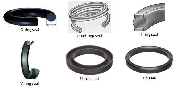
Fig. 17.6: Common Seals
17.8.1 Seal Material
Both metallic and non-metallic materials are used for fabrication of seals used in hydraulic systems. Material hardness is an important characteristic for specific applications. Dynamic seals need to be softer as it helps in better sealing action through compression. Common seal materials are leather, elastomers, nitrile, silicone, neoprene.
Last modified: Saturday, 15 March 2014, 10:30 AM