Site pages
Current course
Participants
General
Module 1. Hydraulic Basics
Module 2. Hydraulic Systems
MODULE 3.
MODULE 4.
MODULE 5.
MODULE 6.
MODULE 7.
MODULE 8.
LESSON 19. Pumps working and Performance
19.1 Introduction
Mechanical energy is converted into hydraulic energy with the help of pumps. Rotations are provided to the pump with the help of an electric motor , which creates a partial vacuum in the inlet of the pump and allows the fluid into the pump through inlet pipe . The fluid so entered is being pushed by the pump into the various components of hydraulic system or machine. There is a misconnect that a pump generates pressure, it only make the flow of fluid. Pressure occurs when the flow from the pump is subjected to a resistance and it forces the liquid into the hydraulic system or hydraulic equipment.
19.2 Positive Displacement Pumps
Generally positive displacement pump has an extremely close fit between the pumping element and the pump housing, which results in very low or negligible slippage. In the positive displacement pump the flow enters and leaves the pump at same velocity and no change in the kinetic energy takes place. A positive displacement pump causes a fluid to move by trapping a fixed amount of it and then forcing the trapped volume of fluid into the discharge pipe.
19.2.1 Positive displacement types
A positive displacement pump can be further classified depending upon the mechanism used -
- Rotary pump
Rotary pump may be of various types like - gear type, screw type, vane type etc. It works on the principle that a rotating gear, screw, or vane traps the liquid at both suction side of the pump and forces it to the discharge side of the pump. In this type of pump generally priming is not required .This type of pumps are having close clearance between the rotary element and the housing and hence rotated at low speeds.
Gear Pump
The basic gear pump consists of two meshed gears , a housing to house the gears. One of the gear is connected to the drive shaft and other is driven as it is meshed with driver gear. .This type of pumps are capable of developing a very high pressure and it delivers a fixed quantity of fluid per revolution of pump shaft. These are simple in design and compact in size and used in moving equipment etc. There may be the following types of gear pumps-
Spur gear pump
Internal gear pump
Screw pump
Lobe pump
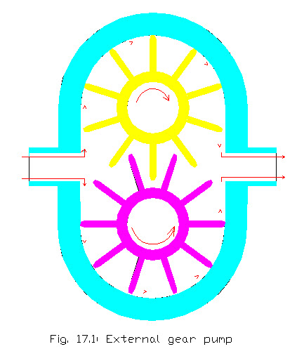
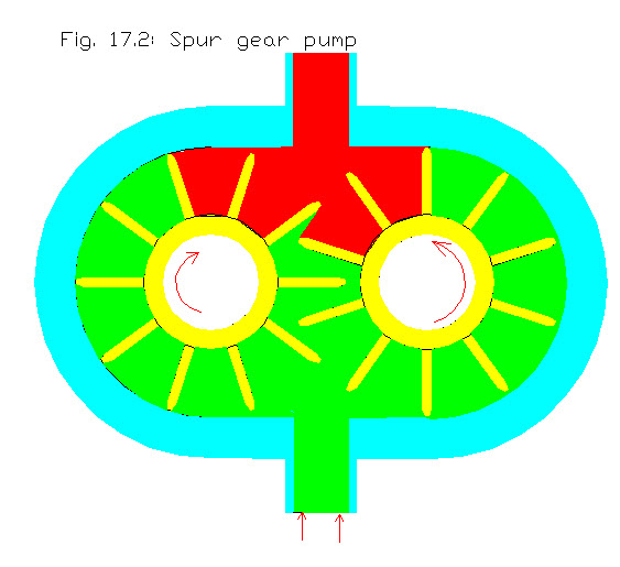
Spur Gear Pump
It consists of a driving gear and a driven gear enclosed in a closely fitted housing. Both the gears move in opposite directions and mesh at a point in the housing between the inlet and outlet ports. Both sets of teeth project outward from the center of the gears. As the teeth of the two gears separate, a partial vacuum forms and draws liquid through an inlet port into the housing is trapped between the teeth of the two gears and the fluid is discharged through the housing to the discharge side. The liquid then pushed through the outlet as the rotating gears develop sufficient pressure.
The velocity of fluid flowing through the pump can be given as-
![]()
Where,
v = velocity
Q = Flow rate
A = Area
Volume of fluid can be calculated as-
Let V = volume of fluid
D1 = outer diameter of gear teeth
D2 = inner diameter of gear teeth
N = speed of pump (rpm)
w = gear teeth width
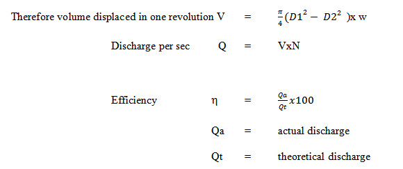
Performance of Pump
Internal Gear Pump
Internal gear pumps used in hydraulic systems are versatile, efficient and produces less noise. It is consisted of internal gear, outside ring gear set offcenter. There is a stationary spacer between the two gears around which oil is carried. Liquid enters the suction port between the large exterior gear and the small interior gear teeth. Liquid travels through the pump between the teeth of the gear-within-a-gear principle. The spacer divides the liquid and acts as a seal between the suction and discharge ports. The large exterior gear and the small interior gear teeth mesh completely to form a sort of seal and forces the liquid out of the discharge port.
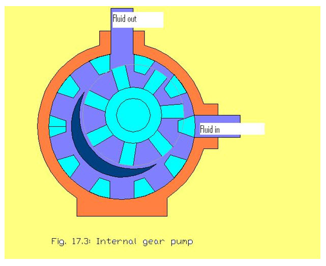

In the internal gear pump the internal gear is coupled with the drive shaft and the external gear is rotated or vise versa. It is a positive displacement pump and used for low pressure system to high pressure systems.
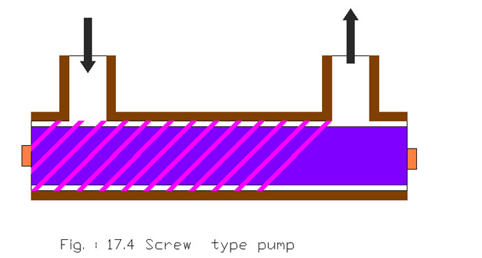
Screw Pump
This type of pumps are a little complicated type of rotary pumps as compared to other types. It is having two or three screws with opposing thread and in this type one screw turns clockwise, and the other anticlockwise. The screws are each mounted on shafts which moves parallel to each other. These shafts also have gears on them that mesh with each other in order to turn the shafts together and keep everything in place. The rotation of the screws, and subsequently the shafts to which they are mounted, draws the fluid through the pump. The clearance between moving parts and the pump housing is kept quite less.
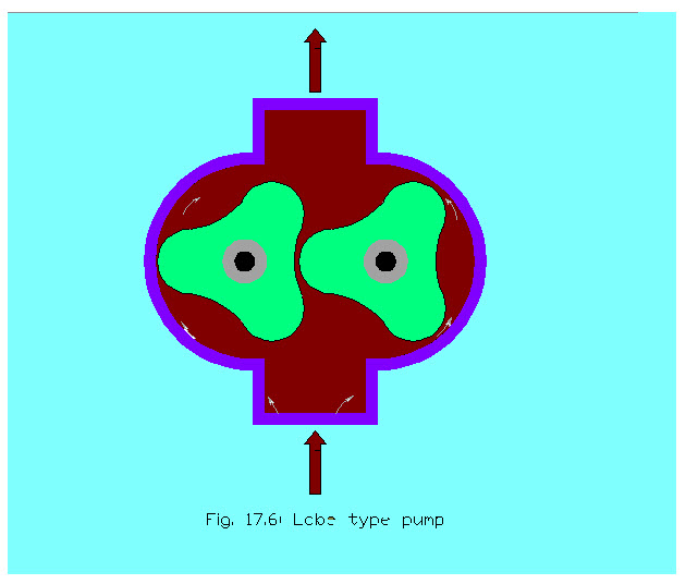
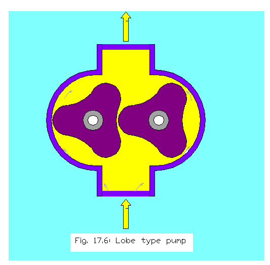
 Lobe Pump
Lobe pumps are rotary type of pumps which are positive displacement pump. A positive displacement pump operates by trapping a fixed amount of fluid from tank or inlet pipe and then forced the trapped volume into a delivery pipe. In this two lobes are used to rotate one against the other, creating two chambers between the lobes and the of pump housing. One of the lobe is driven by the power source where as other is rotated by the timing gear. As the lobes un-mesh on the intake side, they create a cavity with an expanding volume. And hence , the fluid is trapped between the lobes and the housing of pump and moved from suction side to the delivery side. The capacity of material being pumped can be changed by varying speed of the pump.
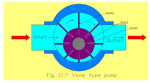
Vane pump
The rotary vane pump is consisted of rotor and stator. The stator is the stationary enclosure in which the rotor rotates. The rotor is mounted with eccentric and therefore the rotor makes contact with the stator at the top of the stator between the inlet and the outlet. This point is called the contact point and is actually in close contact separated only by a thin film of oil. The sliding vanes move in and out of the rotor, making contact with the stator surface. The vanes can be spring-loaded or slide by centrifugal force. These are high volume pumps which can pump at higher pressures .When the rotor rotates within the stator , at the inlet of the pump one of the vanes and the contact point create a large volume which is initially void of molecules. This allows the fluid to to enter the pump. As it enters inside the pump, the fluid is trapped between the rotor vanes and the stator during rotation, it is pushed out through the outlet of the pump..
Reciprocating Pump
This type of pumps are normally consisted of piston, cylinder, crank with connecting rod delivery and suction pipe, etc. Operation of reciprocating motion is done by the power source ytglike electric motor or an engine, etc. Power source gives rotations to the crank through the connecting rod which is subsequently converted into reciprocating motion of piston in the cylinder. When crank moves from inner dead centre to outer dead centre vacuum will create in the cylinder. When piston moves outer dead centre to inner dead centre and piston force the fluid at outlet or delivery value. The reciprocating type pump may be of axial piston pump or radial piston type pump.
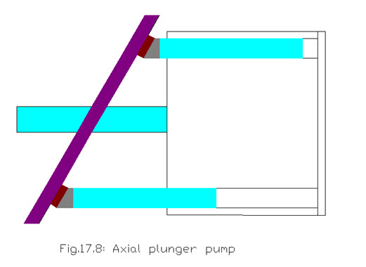
Axial Piston pump
An axial piston pump is that type of pump, which uses the contact between the a swash plate and rotating piston to convert rotary motion of shaft to linear motion of pistons. Axial piston pumps may be an in-line or angle type. Efficiency of this pumps is high, and pumps generally have better durability. In an in-line piston pump , a drive shaft and cylinder block are on the same centerline. Reciprocation of the pistons is accomplished by a swash plate . In the axial piston pump the pistons reciprocate parallel to the drive shaft. Generally the pistons are fitted around a cylinder block which turns also. Displacement in this type of piston pump is found by the size and number of pistons as well as the length of stroke. This variabledisplacement piston pump changes the length of the stroke continuously to match the changing flow requirements of the hydraulic system. Each piston is fitted with a ball joint shoe and each shoe has a flange. As the swash plate is rotated, the pistons will be forced into and out of the their respective bores as the cylinder block rotates. When the swash plate is not rotated, the pistons remain stationary in their bores as the cylinder block is turned and no oil is pumped.
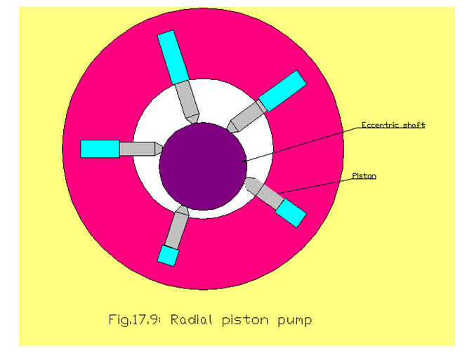
Radial Piston Pump
Radial piston pumps are compact and reliable. These are capable of builting high pressure, high volume and high speed. It is having a number of closely fitted parts and therefore wear is also considered to be more. In this type of pump , the pistons are arranged like wheel
spokes in a short cylindrical block. There are many types of designs of radial piston pump . In this type of pump the pistons are arranged radially around an eccentric cam . The cam is a part of the main shaft. As the shaft rotates the pistons are reciprocated in the cylinders which are oriented radially . As the piston moves inwards the suction is caused and the space in the cylinder is filled with the fluid . When the piston moves outwards the fluid filled inside the cylinder forced outside the cylinder to the delivery side.
fig.
Last modified: Saturday, 15 March 2014, 11:17 AM