Site pages
Current course
Participants
General
Module 1: Formation of Gully and Ravine
Module 2: Hydrological Parameters Related to Soil ...
Module 3: Soil Erosion Processes and Estimation
Module 4: Vegetative and Structural Measures for E...
Keywords
Lesson 24 Bunds
24.1 Introduction
Bunding is an engineering soil conservation measure used for retaining water and creating obstruction to the surface runoff for controlling soil erosion. Bunds are simple earthen embankments of varying lengths and heights, constructed across the slope. When they are constructed on the contour of the area, they are called as contour bunds and when a grade is provided to them, they are known as graded bunds. For bunding, the entire area is divided into several small parts; thereby the effective slope length of the area is reduced. The reduction of the slope length causes not only reduction of the soil erosion but also retention of the runoff water in the surrounding area of the bund. Bunds are similar to the narrow based terrace, but no agricultural practices are done on bunds except at some places, where some types of stabilization grasses are planted to protect the bund.
24.2 Types of Bunds
Bunds are of two types: (1) Contour bund and (2) Graded bund
(1) Contour Bund
When the bunds are constructed following the same contour, they are called contour bunds. Fig 24.1 shows the layout of contour bunds in the field. Contour bunds are recommended for areas with low annual rainfall (<600 mm), agricultural field with permeable soil and having a land slope < 6%. The major requirements in such areas are prevention of soil erosion and conservation of rain water in the soil for crop use.
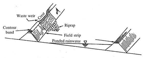
Fig. 24.1. Layout of contour bunds in field. (Source: Das, 2002)
Contour bund absorbs the runoff water stored at the upstream side of the bund. Proper height of the bund is necessary to avoid overtopping during floods. During monsoon, even in a low rainfall region, the entire runoff water cannot be stored and the excess is liable to flow over the bund. To avoid damage, waste or surplus weir (Fig. 24.2) is provided on the bunds to dispose off excess water into the next bund. This prevents water-logging.
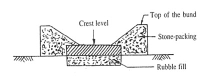
Fig. 24.2. Clear overfall stone weir. (Source: Das, 2002)
Contour bunding can be adopted on all types of permeable soil except for the clayey or deep black cotton soils as these soils have the problem of crack development causing bund failure. Clayey soil also has the problem of water-logging near the bund section, which makes the bund construction infeasible.
(2) Graded Bund
When a grade is provided along the bund for safe disposal of runoff water over the area between two consecutive bunds, they are called graded bund. Graded bunds are adopted in case of high or medium annual rainfall (>600 mm) and relatively less permeable soil areas. Graded bunds are designed to dispose excess runoff safely from agricultural field.
24.3 Design of Bunds
24.3.1 Design of Contour Bund
The design parameters required for contour bunds are
(1) Vertical interval
(2) Horizontal interval
(3) Bund cross-section
(4) Earth work due to bunding
Height of the contour bund should be enough to store the expected peak runoff for a 10 years recurrence interval. A free board of about 20% should be provided for the settlement of height.
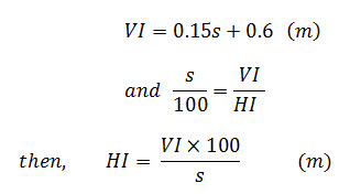
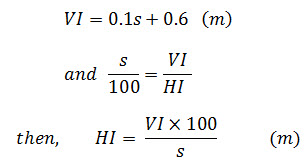
(1) Calculation of Vertical Interval (V.I) and Horizontal Interval (H.I)
For low rainfall areas
Where,
VI = Vertical interval, m
HI = Horizontal interval, m
s = Original land slope, %
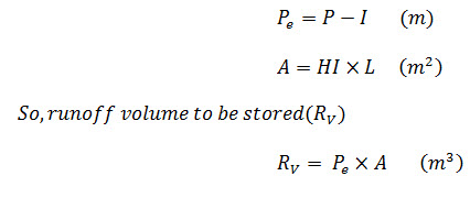
(2) Calculation of Storage Required for Runoff Volume
Where,
P = Precipitation, m
Pe = Excess rainfall depth or surface runoff, m
I = infiltration depth, m
H.I = Horizontal interval, m
L = Length of bund behind which the runoff is stored, m
A = Area of watershed behind two bunds, m2.
RV = Runoff volume to be stored, m3.
(3) Calculation of Storage Volume
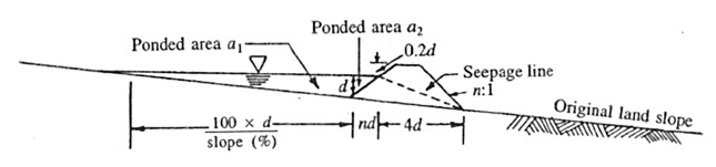
Fig. 24.3. Layout of contour bund. (Source: Das, 2002)
From the above layout of contour bund (Fig. 24.3),
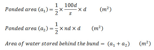
Storage volume (SV) = area of water stored behind the bund × length of bund (m3)
where,
d = depth of water stored behind the bund (m)
n : 1(H:V) = side slope of the contour bund
4:1 (H:V) = Seepage line slope of the bund
(4) Calculation of Depth of Water Stored Behind Bund
For total runoff absorbed by the bund,
Runoff volume (RV) = Storage volume (Sv)
Using this relationship, the depth of water stored behind bund is calculated.
(5) Calculation of Bund Cross Section
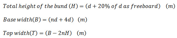
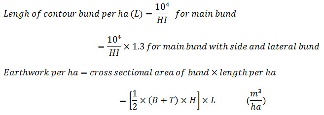
(6) Calculation of Earth Work due to Bunding
24.3.2 Design of Graded Bund
Graded bund is designed based on 1h rainfall intensity for desired recurrence interval. In general, a grade of 0.2 to 0.3% is provided in graded channel. In graded bund free board of 15 to 20% of desired depth is provided.
Recommended Dimension
Height of bund ≤ 45 cm
Top width = 30 to 90 cm
Velocity of runoff should be less than critical velocity.
Table 24.1 Recommended side slope for graded bund (Source: Das,2002)
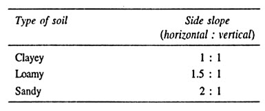
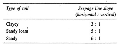
Table 24.2 Recommended seepage line slope for graded bund (Das, 2002)
(1) Calculation of Vertical Interval (VI) and Horizontal Interval (HI)
For medium to high rainfall areas:
Where,
V.I = Vertical interval, m
H.I = Horizontal interval, m
s = Original land slope, %
(2) Calculation of Peak Runoff Rate:
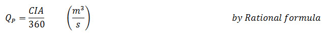
Where,
QP = Peak runoff rate (m3/s)
C = Runoff coefficient
I = Rainfall intensity (mm/h) for duration equal to time of concentration.
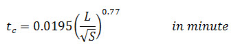
Where,
tc = Time of concentration (min)
L =Length of water flow = (length of bund + distance between two bunds) in (m)
S = H/L = gradient or slope causing water flow
H = Elevation difference causing water flow
= (elevation difference causing length of bund + elevation difference of land)
= ( L Χ g + HI Χ s ) (m)
g = grade of channel (%)
A= Drainage area (ha)
= ( L Χ HI )
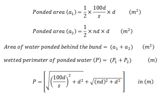
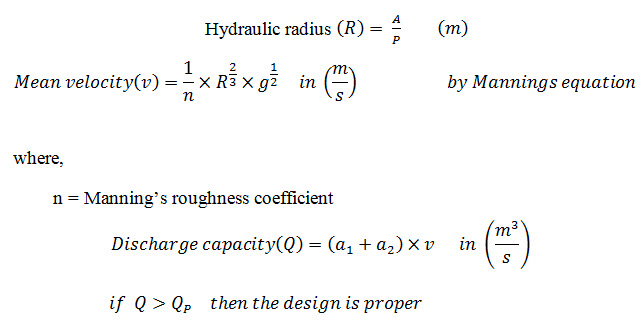
(3) Calculation of Discharge Capacity of Graded Bund
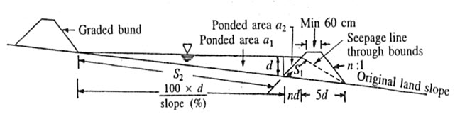
Fig. 24.4. Design layout of graded bund. (Source: Das, 2002)
From the design layout of contour bund (Fig. 24.4),
Where,
d = depth of water stored behind the bund (m)
n:1(H:V) = side slope of the graded bund
5:1 (H: V) = Seepage line slope of the bund for sandy loam soil
(4) Calculation of Bund Dimension
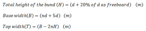
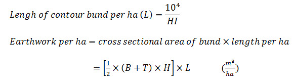
(5) Calculation of Earth Work due to Bunding
24.3.3 Bund Construction
In India, construction of bund is done by manual labour, but bullock-drawn buck scrapers, tractor plough, tractor pulled grade terraces, bulldozers and motor graders are also popular.
Last modified: Monday, 23 September 2013, 9:37 AM