Site pages
Current course
Participants
General
Module 1: Formation of Gully and Ravine
Module 2: Hydrological Parameters Related to Soil ...
Module 3: Soil Erosion Processes and Estimation
Module 4: Vegetative and Structural Measures for E...
Keywords
Lesson 25 Grassed Waterways
25.1 Introduction
Vegetated drainage channels are also called grassed waterways, or vegetated waterways. Such types of channels are either naturally formed or constructed as water courses and planted with grasses. These channels are used for the carrying excess runoff from crop land safely without scouring the channel beds and sides towards the outlets, which may be rivers, reservoirs, streams etc. The vegetated outlets are constructed prior to the construction of terraces, bunds, etc. because grasses take time to establish on the channel bed. Generally, it is recommended that there should be a gap of one year between the construction of grassed water ways and the construction of terraces so that the grasses can be established during the intervening rainy season. Fig. 25.1 shows the grassed waterways.
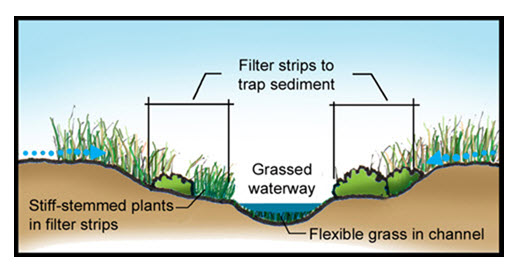
Fig. 25.1. Vegetated waterways (sectional view). (Source: https: //www. nac.unl.edu)
25.2 Factors Affecting the Shape of Waterways
The shapes of grassed waterways are of three types:
(1) Trapezoidal
(2) Triangular
(3) Parabolic
Different shapes of grassed waterways are illustrated in fig. 25.2.
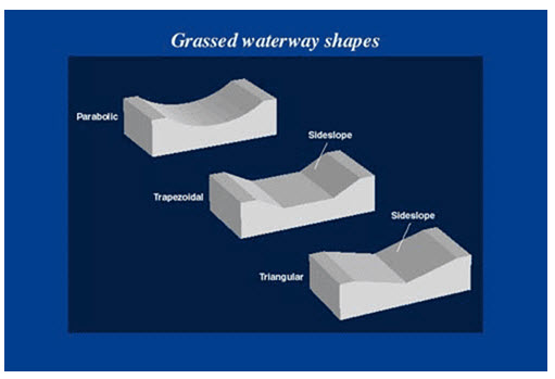
Fig. 25.2. Grassed waterways shapes. (Source: https: //www. www.thisland.illinois.edu)
A parabolic shaped waterway represents a natural channel. In normal course of water flow, the trapezoidal and triangular sections become parabolic in shape due to deposition of sediments over the channel section and bank erosion. At some places earthwork is also not necessary to construct the parabolic shape waterways, only construction of boundaries is needed to define them. The factors that affect the selection of shape of waterways are:
(a) Construction equipment availability
(b) Velocity of flow
(c) Grade of the waterway
(d) The type of grass cover
(a) Construction Equipment Availability
The equipment available for construction of the waterway is one of the main factors. Trapezoidal shaped channel can easily be constructed with the blade type machines provided that the design bottom width of the channel is greater than the minimum width of the cut of the equipment. If the design bottom width of the trapezoidal channel is narrower than the width of the mower swath, then construction is not possible, because neither equipment can move nor desired width of the waterway can be achieved. Similarly, triangular and parabolic shaped channel with side slope of 4:1 or flatter can easily be constructed by using suitable equipment. However, from construction point of view, the trapezoidal cross section can easily be constructed and widely used where the waterway is artificially constructed as terrace outlets along the boundary line. Trapezoidal and triangular cross-section of channel, after some time, is liable to take the form of parabolic section either due to siltation at the bottom or due to scouring of the soil from its bottom and sides. That is why parabolic shape of grassed waterway is generally considered as most economical and also a more stable cross section.
(b) Velocity of Flow:
The permissible flow velocity in the grassed waterway depends upon the type and condition of vegetation and its density to resist the erosion. A uniform vegetative cover in the waterway is important to provide a better channel stability and also to decide the permissible flow velocity. Permissible velocity in grassed waterways varies according to the vegetative growth. The approximate values of permissible flow velocity for different grassed cover are given as:
Permissible Velocity (m/s) Cover Condition
0.9 to 1.2 Sparse grass cover
1.5 to 1.8 Good grass cover
2.0 to 2.5 Sod of excellent cover
However, for an average condition of grassed cover and channel section, a flow velocity from 1.5 to 2.0 m/s is used for design purposes. In grassed waterways, the average flow velocity is always higher than the actual velocity near the bed, as surface roughness is greater.
(c) Grade of the Waterway
Normally, a channel grade of approximately 5% is recommended for vegetated waterways. A grade of more than 10% is not recommended, as it is likely to become erosive. Vegetated waterways are generally constructed along the direction of the slope.
(d) Grass Cover
The grass cover increases the factor of roughness which reduces the velocity of flow and the channel hydraulic capacity, and along with it, the velocity is made safe (non-erosive) for the runoff to pass through the channel. The value of Manning’s roughness factor (n) is not constant for any given species of grass, but varies with the depth and the velocity of flow and the submergence level of grass. When the depth of flow is less, the water seeps through the stems of the grass, which reduces the flow velocity considerably as the resistance to the flow is very high with a high value of n.
25.3 Design of Grassed Waterways
In cases, where the shape of the waterway, the carrying capacity, and the slope of the bed are known, the procedure for the design of the channel parameters comprises of the following steps. This procedure is an iterative one.
Step 1: Assume the value of flow depth and calculate the channel cross sectional area (A), wetted perimeter (P), hydraulic radius (R) and top width (T):
For trapezoidal channel section (Fig. 25.3),
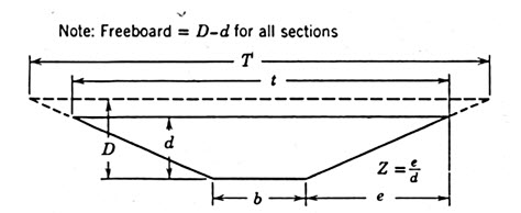
Fig. 25.3. Trapezoidal grassed waterways. (Source: Schwab et al., 1993)
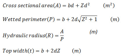
Where,
b = bottom width (m)
d = channel depth (m)
Z = e/d =side slope (horizontal: vertical) of trapezoidal channel
For Triangular channel section (Fig. 25.4),
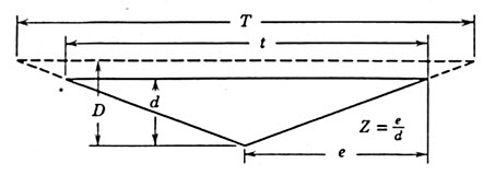
Fig. 25.4. Triangular grassed waterways. (Source: Schwab et al., 1993)
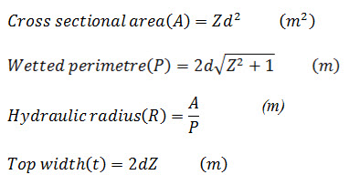
Where,
d = depth of channel (m)
For parabolic channel section (fig. 25.5),
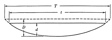
Fig. 25.5. Parabolic grassed waterways. (Source: Schwab et al., 1993)
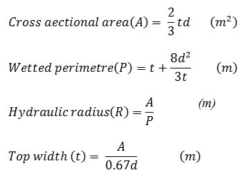
Where,
d = depth of channel section (m)
Step 2: Determine the mean velocity of flow by using manning’s formula which states that

Where,
R= hydraulic radius of the channel section (m)
S = channel grade
n = Manning’s roughness co-efficient (for vegetated waterways, n= 0.04)
Step 3: Determine the discharge rate Q = Av (m3/s) through the channel.
Step 4: Check if the velocity is safe, and the carrying capacity of the channel is within the permissible range.
Step 5: If it is observed that the velocity is unsafe, and the carrying capacity is not within the permissible range, and then repeat the process with another set of assumed value in step (1), till the carrying capacity is found to be within the permissible range.
Step 6: A free board of 15 cm is then added to the assuming channel depth as
