Site pages
Current course
Participants
General
Module 1:Water Resources Utilization& Irrigati...
Module 2:Measurement of Irrigation Water
Module 3: Irrigation Water Conveyance Systems
Module 4: Land Grading Survey and Design
Module 5: Soil –Water – Atmosphere Plants Intera...
Module 6: Surface Irrigation Methods
Module 7: Pressurized Irrigation
Module 8: Economic Evaluation of Irrigation Projec...
Topic 9
LESSON 6. Weirs
6.1 Introduction
Effective use of water for irrigation requires that flow rates and volumes be measured and expressed quantitatively. Measurement of flow rates in open channels is difficult because of non-uniform channel dimensions and variations in velocities across the channel. A weir is a calibrated instrument used to measure the flow in an open channel, or the discharge of a well or a canal outlet at the source.
6.1.1 Terms Used
- Weir Pond: Portion of the channel immediately upstream from the weir.
- Weir Crest: The edge over which the water flows is the weir crest.
- Broad-crested weir: A weir having a horizontal or nearly horizontal crest sufficiently long in the direction of flow.When the crest is "broad", the streamlines become parallel to the crest invert and the pressure distribution above the crest is hydrostatic.
- Sharp Crested Weir: A weir having thin- edged crest such that the over flowing sheet of water has the minimum surface contact with the crest. A sharp-crested weir allows the water to fall cleanly away from the weir, e.g., V notch, Cipolleti weir etc. Fig. 6.1 shows sharp crested weir.
- Head: The depth water flowing over the weir crest measured at some point in the weir pond.
- End Contraction: The horizontal distance from the ends of the weir crest to the sides of the weir pond.
- Weir Scale or Gauge: The scale fastened on the sides of the weir or on a stake in the weir pond to measure the head on the weir crest.
- Nappe: The sheet of water which overflows a weir is called a nappe.
6.1.2 Advantages of Weirs
a) Capable of accurately measuring a wide range of flows
b) Can be both portable and adjustable
c) Easy to construct
d) Tends to provide more accurate discharge rating than flumes and orifices
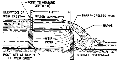
Fig. 6.1.Profile of a Sharp-crested weir.
(Source:http://www.flowmeterdirectory.com/flowmeter_artc_02021403.html accessed on July 28, 2013)
6.1.3 Disadvantages of Weir
a) Relatively large head required, particularly in free flow condition.
b) The upstream pool must be maintained clean of sediment and kept free of weeds and trash. Otherwise, measurement accuracy will be compromised.
6.2 Classification of Weirs
Weirs are classified based on the shape of their opening or notch. The edge of the opening can be either sharp or broad-crested.
6.2.1 Sharp-Crested Weir
These are generally used for water measurement on the farm. They are generally of three types depending upon the shape of notch. These are
- Rectangular Weir
- Cipoletti Weir or Trapezoidal Weir
- V Notch Weirs or Triangular Weir
Fig. 6.2 shows different types of sharp created weirs.
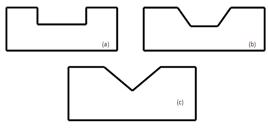
Fig. 6.2. Sharp created weirs (a) rectangular, (b) Cipoletti or trapezoidal and (c) V-notch or triangular.
6.2.2 Broad-crested Weirs
A weir that has a horizontal or nearly horizontal crest sufficiently long in the direction of the flow so that the nappe will be supported and hydrostatic pressures will be fully developed for at least a short distance. Broad crested weir is shown in Fig. 6.3.
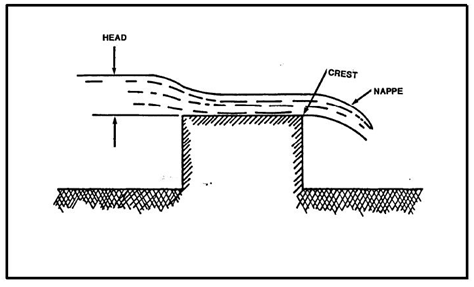
Fig. 6.3. Broad crested weir.
(Source: http://navalfacilities.tpub.com/mo221/mo2210113.htm, accessed on Aug 14, 2013)
Weirs may also be classified as suppressed and contracted.
6.2.3 Suppressed Weir
A rectangular weir whose notch or opening sides are coincident with the sides of the approach channel, also rectangular, which extend unchanged downstream from the weir. It is the lateral flow contraction that is “suppressed”. Fig. 6.4 shows suppressed and contracted rectangular weir.
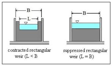
Fig. 6.4. Suppressed and contracted rectangular weir.
(Source:http://www.brighthubengineering.com/hydraulics-civil-ngineering/88804-calculations-for-rectangular-weir-flow-equations/, Accessed on Aug 14, 2013)
6.2.4 Contracted Weir
The sides and crest of a weir are far away from the sides and bottom of the approach channel. The nappe will fully contract laterally at the ends and vertically at the crest of the weir. Also called an “unsuppressed” weir.
6.3 Rectangular Weirs
Rectangular weir takes its name from the shape of its notch. The discharge through a weir or notch is directly related to the water depth (H), (Fig. 6.5) and H is known as the head. This head is affected by the condition of the crest, the contraction, the velocity of approaching stream and the elevation of the water surface downstream from the weir. Rectangular weirs can be suppressed, partially contracted, or fully contracted.
6.3.1 Derivation of Equation
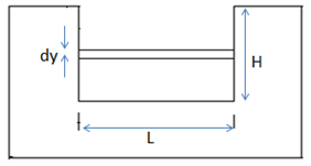
Fig. 6.5.Definition sketch for rectangular weir.
Consider Fig. 6.5
Cross sectional area = a = L.dy .........(6.1)
Velocity,
![]() .........(6.2)
.........(6.2)
Total discharge
![]() .......(6.3)
.......(6.3)
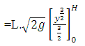
![]()
![]() ......(6.4)
......(6.4)
Let
![]() = Discharge coefficient of weir.
= Discharge coefficient of weir.
So, ![]() ............(6.5)
............(6.5)
If Q = lt/s, L and H in cm then,
![]() .......,(6.6)
.......,(6.6)
For one side contraction,
![]() ...........(6.7)
...........(6.7)
For both side contraction,
![]() .............(6.8)
.............(6.8)
Example 6.1:
Water flows through a contracted rectangular weir 120 cm long to a depth of 30 cm, it then flows along a rectangular channel 150 cm wide and over a second weir which has length equal to the width of the channel. Determine the depth of water over the second weir.
Solution:
The first weir is contracted, i.e. both end contracted.
Given,
Length of the weir (L) = 120 cm
Depth of water over the weir (H) = 30 cm
So, Discharge of flow = ![]()
= ![]()
= 344.67 L/sec
In second weir, length of the weir (L) =150 cm
Discharge through first weir and second weir is same.
Let assume, depth of water over second weir is = H cm
Now, ![]()
![]()
H= 24.97 cmAns.
So, the depth of water over the second weiris 24.97 cm.
6.4 Cipoletti Weirs
The Cipolletti weir (Fig. 6.6) is trapezoidal in shape. The slope of the sides, inclined outwardly from the crest, should be one horizontal to four vertical. The selected length of notch (L) should be at least 3H and preferably 4H or longer. Cipoletti weirs are considered fully contracted.
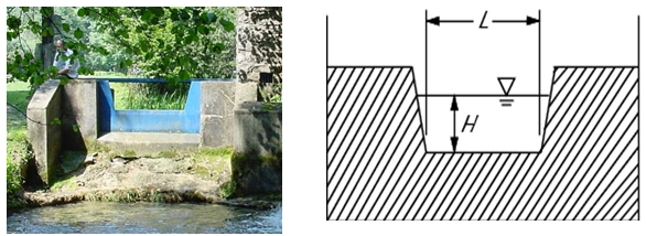
Fig. 6.6 Cipoletti weirs.
Discharge through Cipoletti weir is calculated as:
![]() (6.9)
(6.9)
Example 6.2:
A Cipoletti weir has a breadth of 60 cm at its crest. The head of water flowing over the crest is 30 cm. Determine its discharge.
Solution:
Given,
Crest width (L) = 60 cm
Head of flow over the crest (H) = 30 cm
So, discharge through the weir (Q) = ![]()
![]()
= 183.37 L/sec
Discharge of Cipoletti weir is 183.37 L/sec Ans.
6.5 V- notch Weir
In this case, the notch is “V” in shape. Depth of water above the bottom of the V is called head (H). The V-notch design causes small changes in discharge hence causing a large change in depth and thus allowing more accurate measurement than with a rectangular weir. Head (H) should be measured at a distance of at least 4H upstream of the weir.
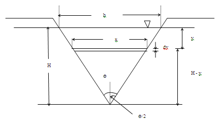
Fig.6.7.Triangular notch weir.
Derivation of Equation:
Consider the Fig. 6.7,
Crosssectional area, dA = xdy (6.10)
Velocity of flow, V = ![]() (6.11)
(6.11)
dQ = xdy. ![]() (6.12)
(6.12)
By Similar triangles ![]() and
and ![]()
On Substituting and integrating both sides of Eq. 6.12,
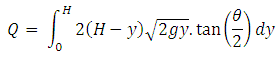
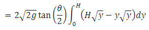
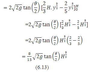
![]() (6.14)
(6.14)
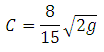
Where,
![]() (6.15)
(6.15)
If Θ =900 then
For Θ=900, H in cm and Q in L/s
![]() (6.16)
(6.16)
Example 6.3:
Determine discharge of 90o V-notch having 30 cm head of flow.
Solution:
Discharge through V-notch ![]()
![]()
= 68.02 L/sec
So, Discharge through 90o V-notch having 30 cm head of flow is 68.02litres/sec.
6.6 Operation & Limitations
Properly constructed and installed weirs provide most accurate flow measurement. However improper setting and operation may result in large errors in the discharge measurements. To ensure reliable results in measurement, the following precautions are necessary in the use of weirs.
- The weirs should be set at lower end of a long pool sufficiently wide and deep having smooth flow at velocities less than 15cm/sec.
- Baffles may be put in weir pond to reduce velocity.
- The weir wall must be vertical.
- The center line of the weir should be parallel to the direction of flow.
- The crest of weir should be level so that water passing over it will be of the samedepth at all points along the crest.
- Notch should be of regular shape and its edge must be rigid and straight.
- The weir crest should be above the bottom of the approach channel.
- The crest of weir should be placed high enough so that water will fall freely below weir.
- The depth of water flow over the rectangular weir should not less than about 5 cm and not more than about 2/3 crest width.
- The scale or gauge used for measuring the head should be located at a distance of about four times the approximate head. Zero of scale should be exactly at the same level as the crest level of the weir.
Limitations of Weirs:
- Weirs are not always suitable for measuring flow. Sufficient head is required for operating any type of weir.
- They are not accurate unless proper conditions are maintained.
- They require a considerable loss of head which is mostly not available in channels on flat gradients.
- Weirs are not suitable for water carrying silt.
- Weirs are not easily combined with turnout structures.
References
Michael, A.M. (2008). Irrigation Theory and Practice. Vikas Publishing
House Pvt. Ltd., Delhi.
ecourses.vtu.ac.in/nptel/courses/Webcourse.../parshall_flumes.pdf
nptel.iitm.ac.in/courses/IIT-MADRAS/Hydraulics/pdfs/.../13_1b.pdf
http://agriinfo.in/default.aspx?page=topic&superid=8&topicid=64
http://www.alterra.wur.nl/Internet/webdocs/ilri.../pub20-h1.2.pdf
Suggested Reading
Michael, A.M. (2008). Irrigation Theory and Practice. Vikas Publishing
House Pvt.Ltd., Delhi.
http://agriinfo.in/default.aspx?page=topic&superid=8&topicid=64
nptel.iitm.ac.in/courses/IIT-MADRAS/Hydraulics/pdfs/.../13_1b.pdf
Last modified: Wednesday, 16 April 2014, 10:29 AM