Site pages
Current course
Participants
General
Module 1. Introduction about design and developmen...
Module 2. Study of special design features of trac...
Module 3. Study of basic design parameters for tra...
Module 4. Selection of different mechanical power ...
Module 5. Study of tractor steering and suspension...
Module 6. Design and analysis of tractor hitch sys...
Module 7. Design of a tractor hydraulic system
Module 8. Study of electrical, electronics and gui...
Module 9. Ergonomics, controls and safety features...
Module 10. Tractor testing
Module 11. General revision
Appendices & References
Lesson 7. Soil machine systems for off-road vehicles
1. Introduction
The agricultural tractor is one of the class of mobile machines that involves the ‘traction’ process. The word 'traction' and name 'tractor' come from the word to 'draw' or 'pull' so a tractor is basically a machine for pulling off-rod; other mobile machines such as locomotives are in the same class. Vehicles like trucks and even motor cars, which are essentially vehicles for carrying loads are also involve the on road traction process. The tractor is also in the class of machines that involves operation under what are known as 'off-road' conditions. Others in this class include machines used for earth moving, mining and military work.
The tractor tyres have the function of supporting the tractor and of converting rotary motion of the engine to linear motion of the tractor.
The wheels must be chosen to:
1. Support the weight of the tractor (together with any transferred weight by attached implements) while limiting the sinkage into the soil surface and the resultant rolling resistance.
2. Engage with the soil (or surface) and transmit the traction, braking and steering forces (reactions) while limiting relative movement and the resultant slip, skid etc.
3. Provide ground following ability together with some springing and shock absorption.
The important variables in relation to the tyres include:
1.Size (diameter and width) which determines their tractive capacity and rolling resistance.
2.Strength, expressed in terms of ply rating, which in turn determines the pressure that can be used and hence the weight that the tyre can carry; this in turn also determines the tractive capacity and the rolling resistance.
3.Tread pattern which, together with the surface characteristics, determines the contact with the surface.
The losses in power at the wheel-surface interface are often great, particularly on soft surfaces (i.e., their tractive efficiency is low), hence the power available at the tractor drawbar may be much less than the power of the engine. Therefore the choice of the tyres and the weight on them is crucial in determining the overall performance of the tractor.
Various types of tyres may be used on the tractor, depending mainly on the surface on which it is working. For the following conditions, the tyres or wheels indicated in Fig 7.1 are recommended.
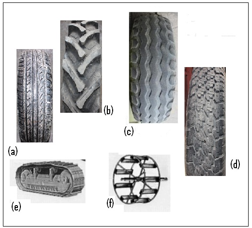
Fig. 7.1: Different types of tyres for different conditions
(a) Large area, shallow tread with 'high' pressure: Hard surfaces such as roads
(b) Intermediate depth tread: Normal agricultural work, dry soil
(c) Deep tread: Soft, wet agricultural soils
(d) Wide low pressure: Lawns/desert where low sinkage is required
(e) Tracks as on a crawler tractor: Dry soil, heavy loads as in earthmoving
(f) Metal cage, with angled lugs, alone or as extensions to normal tyres: Saturated, puddled soils
2. Definitions:
Rolling (motion) resistance, R is the force opposing motion of the wheel that arises from the non-recoverable energy expended in deforming the surface and wheel. It is convenient to consider this force as acting in the horizontal direction.
Tractive force, H is the horizontal reaction on a driven wheel by the soil in the contact area; it is equal and opposite to the horizontal force generated by the wheel on the soil.
Drawbar pull, P is the horizontal force at the axle generated by a driven wheel; it may be assumed that:
Drawbar pull (P) = Tractive force (H) - Rolling resistance (R) ...(7.1)
Towing force is the force to move a freely rolling wheel over the surface and is equal and opposite to the rolling resistance.
3. Operational states of a wheel
The operation of a wheel can be classified into one of the following states; each occurs within the tractor or other machines under some conditions and each has a particular unknown parameter associated with it.
(a) Braked: Here the wheel is towed against an opposing, external torque as when being braked or when it is used to generate a torque to operate a 'ground-driven' machine such as a seed drill; the unknown parameter is the wheel slip. The extreme case is where the wheel does not rotate, but just skids across the surface.
(b) Towed: Here the wheel, such as the front wheel of the tractor or the wheel of an agricultural implement, is towed with zero opposing external torque; the unknown parameter is the rolling resistance. Towed wheel is a special case of the braked wheel, with zero braking torque. A towed wheel is subject to some negative wheel slip.
(c) Driven: Here the wheel is driven with an external input torque and is required to develop a drawbar pull as in the drive wheel of a tractor; the unknown parameter is the wheel slip. The extreme case is where the wheel slips, but does not move forward. These operational states of a wheel in which input and output torque and input and output force (towing force or drawbar pull) are shown plotted against wheel-slip. From this it will be seen that:
(d) Self-propelled: Here the wheel is driven with an external input torque to overcome its own rolling resistance and to propel it across the surface without developing a drawbar pull. This approximates to the drive wheel of a tractor with no drawbar pull (if we neglect the rolling resistance of the front wheels); the unknown parameter is the rolling resistance. Self-propelled wheel is a special case of the driven wheel, with zero drawbar pull. Self-propelled wheel is subject to some positive slip
4. Tractor Performance Analysis:
Thus, if we neglect losses in forward motion due to wheel slip and in drawbar pull due to rolling resistance, all of the power from the engine is available at the drawbar. .But this is the ideal situation which might apply approximately to the tractor working on hard surfaces with small drawbar pulls and small wheel slips.
However, in many agricultural situations, wheel slip is significant, hence the travel speed of the tractor will be lesser than the ideal value. Also, much of the torque on the rear wheels goes to drive the tractor forward against the rolling resistance of both the driving and the rolling wheels. Hence the drawbar pull will also be lesser than the ideal value.
Although the tractor is moving, the equations of equilibrium can be applied to it because it is assumed that there is no acceleration. Force and torque acting on tractor are shown in Fig. 7.2.

Fig 7.2: Mechanics of the tractor
5. Speed analysis:
Drive wheel diameter = D
Engine speed = Ne
Drive wheel rotational Speed = Nw
Overall transmission ratio r = Ne/Nw
If we assume that there are no losses in motion due to slip between the wheel and the surface:
Travel speed, Vo = Linear speed of wheels= ![]()
This analysis shows that the travel speed depends directly on the engine speed and inversely on the gear ratio.
If the tractor is now moving with a speed V (lesser than the ideal travel speed, Vo above),
We can then define wheelslip as:
Wheelslip, s = Vo - V/Vo
Where, Vo = theoretical travel speed
V = actual travel speed
![]() ... (7.2)
... (7.2)
6. Torque / force analysis
Engine torque = Te
Drive wheel torque, Tw = r Te
Equilibrium requires that this torque is equal and opposite to the moment of the soil reaction, H on the wheel:
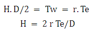
If we assume that there are no other horizontal external forces acting (such as rolling resistance, aerodynamic forces), equilibrium also requires that:
Drawbar pull, P = Soil reaction, H
![]()
This analysis shows that the drawbar pull depends directly on the torque generated by the engine and on the gear ratio. This assumes that the wheel / ground contact can generate the reaction to P.
A rolling resistance force (∑R for all wheels) which is assumed to act horizontally on the wheels at the wheel- ground contact patch, opposes motion of the tractor,
For equilibrium of the external horizontal forces acting on the tractor:
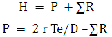 ... (7.3)
7. Power analysis
Considering power transmission at the wheels,
Output power = Input power - Power loss
i.e., Drawbar power = Wheel power - Power loss
Hence, Power loss = Wheel power - Drawbar power
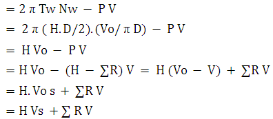 ... (7.4)
Here Vs is the slip velocity, i.e., the velocity of the wheel relative to the surface at the surface- wheel contact.
Total power loss = Power loss due to slip + Power loss due to rolling resistance
Minimizing the total power loss thus is matter of minimizing the sum of the loss due to slip and that due to rolling resistance. This is a complex problem when it is realized, for example, that the effect of weight on the driving wheels is to decrease the slip loss and increase rolling resistance losses.
8. Tractor Performance Efficiencies:
(a) Tractive efficiency (TE):
TE = Output power/Input power
= Drawbar power/Wheel power
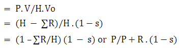 ... (7.5)
The tractive efficiency that appears here contains two terms:
P and (P+R) which represents a ‘force’ efficiency; thus when there is no rolling resistance (R = 0) this factor in the tractive efficiency = 1.
(i) (1-s) which represents a ‘speed’ efficiency; again when there is no wheelslip (s = 0), this factor in the tractive efficiency = 1.
It might be thought that the tractive efficiency, which is one of the most important measures of tractor performance, could be determined on the basis of above mentioned equation.
However, the major difficulty with this approach is that, in practice, it is not possible to determine a relationship between rolling resistance and slip or, in general, to determine rolling resistance when a wheel is undergoing a slip. Hence, it is necessary to determine the tractive efficiency by measuring drawbar and wheel power directly by following relation;
TTE = P V/2 π Tw Nw ...(7.6)
Drawbar pull, P, with a tension load (force) cell between the tractor and a load vehicle or implement
Travel speed, V, by timing over a known distance
Wheel torque, Tw , with a torque load cell in the transmission to the driving wheels
Wheel speed, Nw , by counting wheel revolutions over a known time period
(b) Transmission efficiency (TME)
TME = Power to wheels/Power from engine
![]() ... (7.7)
... (7.7)
The maximum transmission efficiency is dependent on the design and the quality of the transmission elements.
For good quality gears the maximum efficiency is about 98% per pair of gears; hence with, say, 3 pairs of gears in the transmission and another 2 pairs in the differential / final drive, the maximum efficiency will be 0.98x0.98x0.98x0.98x0.98 = 90%.
Little improvement in efficiency can be obtained by more accurate or elaborate gearing; other types of transmission will be no more efficient.
(c) Engine efficiency(EE):
EE= Power from engine/Power in fuel
![]() ...(7.8)
...(7.8)
Where,
FC = fuel consumption rate, kg/min
C = calorific value of the fuel, kJ/kg
The maximum value for engine efficiency is dependent on and strictly limited by the thermodynamics of the engine processes. A maximum value of about 35% for a diesel engine can be expected; other types of engine will, in general, be less efficient.
(d) Overall efficiency (OE):
= Drawbar power/Fuel power
= Engine power/Fuel power. Wheel power/Engine power. Drawbar power/Wheel power
= Engine efficiency. Transmission efficiency. Tractive efficiency
Consider typical maximum values for these variables: ηo = 0.35 x 0.90 x 0.75 = 22 %
Because the maximum tractive efficiency is low and highly variable and the other efficiencies like transmission efficiency or strictly limited efficiency of engine, any significant increase in the overall efficiency of tractor performance will be achieved by increasing the tractive efficiency. Research into an understanding of the traction process and into more efficient traction devices are needed.
9. Tractive coefficient (TC):
The performance of a tractor depends to a significant degree on its weight and, in particular, on the weight on the driving wheels. It is therefore useful to define a non-dimensional drawbar pull - weight ratio termed:
Tractive coefficient (TC)= Drawbar pull/Weight on driving wheels
The tractive coefficient is a number which characterizes the interaction between the wheel and the surface in an analogous way to which coefficient of (sliding) friction characterizes the interaction between one body sliding on another. Where a different wheel and surface may be considered similar to those for which the tractive coefficient is known, then for the same wheelslip:
Drawbar pull = Tractive coefficient x weight on wheel
Where a tractor operates on a slope the tractive coefficient should logically be based on the total force parallel to the ground, ie, on the drawbar pull plus the component of the weight of the tractor down the slope. Where a four-wheel tractor is considered, and with other tractors also, the weight used may be the total weight on all wheels. In quoting values of tractive coefficient, it is therefore necessary to state which weight has been used.
Last modified: Friday, 4 April 2014, 11:59 AM