Site pages
Current course
Participants
General
Module 1: Fundamentals of Reservoir and Farm Ponds
Module 2: Basic Design Aspect of Reservoir and Far...
Module 3: Seepage and Stability Analysis of Reserv...
Module 4: Construction of Reservoir and Farm Ponds
Module 5: Economic Analysis of Farm Pond and Reser...
Module 6: Miscellaneous Aspects on Reservoir and F...
Lesson 5 Earthen Embankments
5.1 Introduction
Earthen embankments have been used since ancient times to impound and divert water. These are simple compacted structures that rely on their mass to resist sliding and overturning and are the most common types of dams found worldwide. Modern haulage methods and developments in soil mechanics towards the end of the nineteenth century have greatly increased the safety and life of these structures.
The main advantages involved in the construction of the earthen dams are:
Use of locally available material in construction
Simple design procedure
Requirement of comparatively small plant and equipment
Flexibility in foundation requirements as compared to the other types of dams. The broad base of an earth dam spreads the load on the foundation.
Higher resistance of earth-fill dams to settlement and movement than rigid structures. So, they are more suitable for areas where earth movements are common.
However the earthen embankments are not free from disadvantages and these are:
An earth embankment is easily eroded by water flowing on, over or against it. Thus, a spillway for removal of excess water and adequate upstream protection are essential for an earth dam.
Design and construction of an effective spillway is usually the most technically difficult part in any dam building work. A site with a poor quality spillway should be avoided.
Inadequately compacted earthen embankment offers weak structural strength and facilitates formation of pathways for preferential seepage.
Earthen dams require continual maintenance against soil erosion, tree growth, subsidence, animal and insect damage and seepage.
5.2 Basic Terminologies
When discussing about the physical characteristics of a dam, the following terminologies are frequently used.
Abutment: An abutment is a sub-structure, natural or artificial, that supports the ends of a dam or bridge. It is the part of the valley wall against which the dam is constructed or the part of the dam that contacts the stream/river bank. An artificial abutment is sometimes constructed, as a concrete gravity section, to take the thrust of an arch dam where there is no suitable natural abutment. Abutments are defined in terms of left and right as looking away from the resevoir towards the downstream (Fig. 5.1).
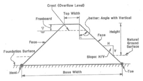
Base Width: The width of the dam measured along the interface of the dam and its foundation.
Breach: It is opening or a breakthrough of a dam sometimes caused by rapid erosion of a section of earth embankment by water.
Conduit: A conduit refers toa closed channel to convey the discharge through or under or around a dam. Usually pipes constructed of concrete, steel or polyvenyl chloride (PVC) material are used for the purpose.
Core: Unless otherwise stated, a core is also known as impervious core or impervious zone.It refers to a zone of material of very low permeability in the body of the embankment to prevent leakage. Based on the position and the material used, these are also termed as central core, inclined core, puddle clay core, and rolled clay core etc.
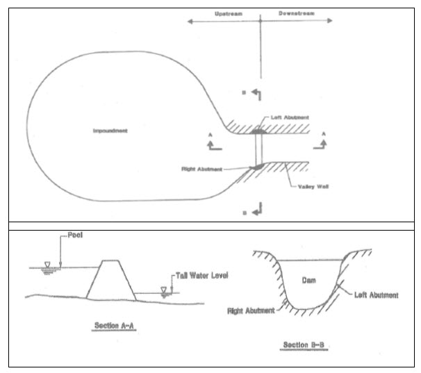
Fig. 5.1. Basic nomenclature of a Dam. (Source: www.des.nh.gov)
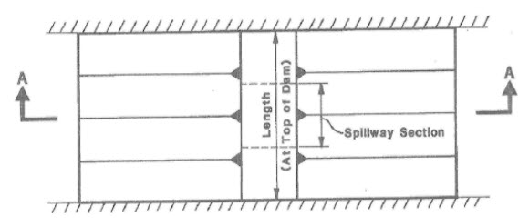
Crest Length: It refers to the length of the top of a dam from left abutment to right abutment. In addition to the length of spillway, it includes the powerhouse, navigation lock, fish pass, etc. where these ancillary structures form a structural part of the dam. These structures should not be included in crest length when they are detached from the dam.
Crest of Dam: The crest of dam refers to the crown of an overflow section of a dam. In other words, it is the elevation of the uppermost surface of a dam excluding any parapet wall, railings, etc.
Crest Width: The width or thickness of a dam at its crest level. In general, the term "thickness" is used for gravity and arch dams and "width" is used for other dams.
Cutoff: An impervious construction by means of which seepage is reduced or prevented from passing through foundation material.
Cutoff Wall: It is a wall made of impervious material such as concrete or asphalt concrete or steel sheet or piling etc. built into the foundation to reduce the seepage rate under the dam.
Drainage Layer or Blanket: It refers to a layer of pervious material placed directly over the foundation material or downstream slope to safely drain the seepage of the embankment. When such a blanket is placed on the impoundment floor and upstream embankment to prevent seepage enering the dam, it is called an upstream blanket.
Drawdown: It is the resultant lowering of water surface level in the reservoir due to release of water.
Embankment: It is made of fill material, usually earth or rock, placed with sloping sides of the dam and usually with a length greater than its height.
Face: The external surface of a structure, such as the surface of a dam or appurtenanceis called as its face.
Flashboard: A length of timber, concrete, or steel placed on the crest of a spillway to raise the retention water level but which may be removed in the event of a flood by manual retrieval, a tripping device or by deliberately designed failure of the flashboard or its supports.
Foundation of Dam: The natural material on which the dam structure is placed. It is often modified to provide more favourable hydraulic characteristics.
Freeboard: The vertical distance between a stated reservoir elevation and the crest of the dam is called as its freeboard (Fig. 5.2). "Net freeboard", "dry freeboard", "flood freeboard", or "residual freeboard" is the expression for the vertical distance between the estimated maximum water elevation and the crest of the dam. "Gross freeboard" or "total freeboard" is the expression for the vertical distance between the maximum normal water elevation and the crest of the dam.
Gate: In general, a device in which a member is moved across the waterway from an external position to control or stop the flow is called as the gate. There are several types of gates in use.
Crest Gate: It is also called as spillway gate. A gate on the crest of a spillway that controls overflow or reservoir water level.
Flap Gate: A gate hinged along one edge, usually either the top or bottom edge. Examples of bottom hinged flap gates are tilting gates and fish belly gates so called from their shape in cross section.
Outlet Gate: A gate controlling the outflow of water from a reservoir is called as an outlet gate.
Radial Gate: It is a gate with a curved upstream plate and radial arms hinged to piers or other supporting structures. It is also called as tainter gate.
Slide Gate: It is a gate that can be opened or closed by sliding in supporting guides. It is also called as a sluice gate.
Heel of Dam: The junction of the upstream face of a gravity or arch dam with the foundation surface is called heel of the dam. In the case of an embankment dam, this junction is referred to as the upstream toe of the dam.
Intake: An intake refers to any structure in a reservoir or dam through which water is drawn into an outlet or measuring flume.
Outlet: It is an opening in a dam through which water can be freely discharged for a particular purpose from a reservoir.
Low Level Outlet: It is an opening at a low level from the reservoir generally used for emptying the impoundment. It is also called as bottom outlet.
Pervious Zone: It refers to a part of the cross section of an embankment dam comprising material of high permeability.
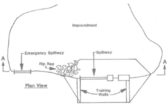
Riprap: It is a layer of stones, broken rocks or precast blocks placed in random fashion on the upstream slope of an embankment dam, on a reservoir shore or on the sides of a channel as a protection against waves, ice action and flowing water. Very large riprap is sometimes referred to as armoring.
Seepage Collar: It refers to a projecting collar usually of concrete or steel built around the outside of a pipe, tunnel or conduit under an embankment dam, to lengthen the seepage path along the outer surface of the conduit.
Spillway: It is a structure over or through which flood flows are discharged (Fig. 5.3). If the flow is controlled by gates, it is considered as a controlled spillway; if the elevation of the spillway crest is the only control, it is considered as an uncontrolled spillway.
Auxiliary Spillway or Emergency Spillway: A secondary spillway designed to operate only during exceptionally large floods.
Shaft Spillway or Morning glory Spillway: A vertical or inclined shaft into which flood water spills and then is conducted through, under, or around a dam by means of a conduit or tunnel. If the upper part of the shaft is splayed out and terminates in a circular horizontal weir, it is termed a "bellmouth" or "morning glory" spillway.
Ogee spillway (ogee section): An overflow spillway, which have an “S” or ogee form of curve in cross section. The shape is intended to match the underside of the nappe at its upper extremities.
Spillway Channel (Spillway Tunnel): It is a channel or tunnel conveying water from the spillway to the river downstream.
Stoplogs: Large logs, timbers or steel beams placed on top of each other with their ends held in guides on each side of a channel or conduit so as to provide a cheaper or more easily handled means of temporary closure than a bulkhead gate.
Structural Height: It is the vertical distance from the lowest point of natural ground on the downstream side of the dam to the highest point of the dam which would impound water.
Toe of Dam: The junction of the downstream face of a dam with the natural ground surface. This is also referred to as the downstream toe.
Top of Dam: The elevation of the upper most surface of a dam, usually a road or walkway, excluding any parapet wall, railings etc.
Top Thickness (Top Width): The thickness or width of a dam at its top is called as top thickness. In general, the term thickness is used for gravity and arch dams; and width is used for other dams.
Training Wall: Training wall is built to confine or guide the flow of water.
Trash Rack: The trash rack is a screen comprised of metal or reinforced concrete bars located in the waterway at an intake so as to prevent the ingress of floating or submerged debris.
PLANE VIEW
SECTION A-A
Fig. 5.2. Dam geometry. (Source: www.des.nh.gov)
PLANE VIEW
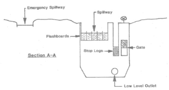
SECTION A-A
Fig. 5.3. Operating element of a dam. (Source: www.des.nh.gov)
Keywords: Embankment, spillway, dam, operating element
References
Garg, S. K. (2011). Irrigation Engineering and Hydraulic Structures. Khanna publishers.
http://des.nh.gov/organization/commissioner/pip/factsheets/db/documents/db-1.pdf
Suggested Readings
Murthy, V.V.N. and Jha. M. K. (2011). Land and Water Management Engineering. Kalyani publication.
Suresh, R. (2002). Soil and Water Conservation Engineering. Fourth edition.
Last modified: Monday, 3 February 2014, 5:27 AM