Site pages
Current course
Participants
General
MODULE 1. Orhtographic Projections of Machine comp...
MODULE 2. Types of joints
MODULE 3. Computer Aided drawing
MODULE 4. Numeric control systems
Topic 5
Topic 6
Topic 7
Topic 8
Topic 9
Topic 10
LESSON 3. Drawing of missing views and different methods of dimensioning
3.1.Introduction
The identification of missing views from the given views is very important which will improve the drawing ability. The different methods of dimensioning is also important to present our drawing in a understandable format.
3.2.Drawing of missing views
Any engineer or technician should have the ability to understand the orthographic views and visualize the original object by analyzing all the views. An engineering drawing is read mentally. The whole drawing cannot be interpreted easily at one glimpse. It should be read analytically and patiently. In an Orthographic projection, two views are necessary to study about the object or understand the nature of the object. Sometimes, the third view is needed to completely envisage the object. It is necessary to create the third view from the two available views so that all the details of the object are obtained. Thus creating the missing view is of importance in orthographic projection.
The meaning of two circles shown in the figure 3.1. can be understood only after studying the other view. The circles may be either projections or holes or both.
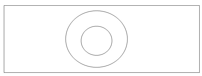
Figure 3.1
Every point and a line in the orthographic projection has a meaning. A point may represent an edge or a corner. A line may be a representation of an edge or a surface. The drawing can be understood only by referring again and gain the views. Then the shape of the object as a whole is to be visualized.
Expertise in reading a drawing can be obtained by projecting one or more views from the given views or by converting the views in to sectional views and analyzing the views.
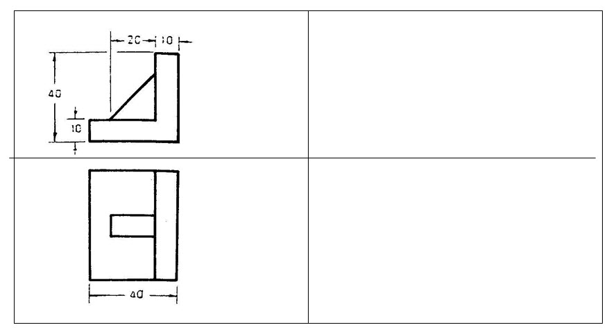
Exercise 1. Two views of an object are shown below. Draw the views and add the side view.
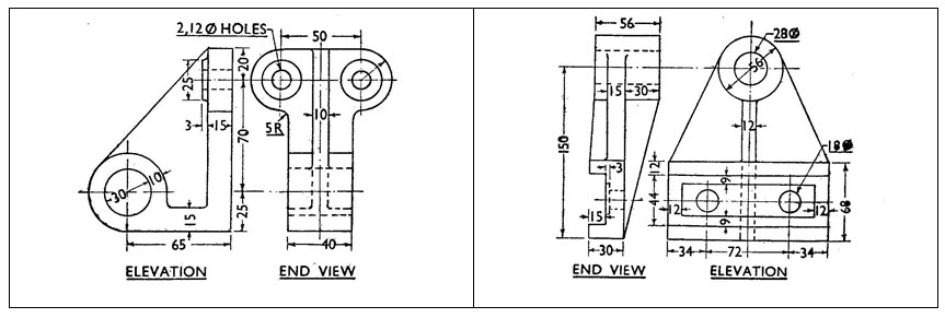
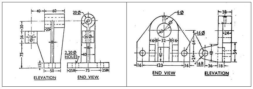
Exercise.2. Draw the given views and also the missing views
3.2.Dimensioning
A drawing without dimensions is of no use to engineers. Though we have the shape of an object in a rough drawing, the exact size of the object has to be clearly illustrated in the drawing. The details which are explained in terms of numerical values of distances, between any two points on a drawing using lines, symbols, notes, units etc., is known as dimensioning.
3.2.1.Types of dimensions
There are two types of dimensions. They are :
a) Dimensions representing the size of the object namely size or functional dimensions (Fig.3.2.a)
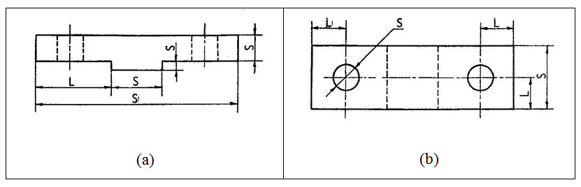
(Fig.3.2)
b) Dimensions showing the actual position or location of a particular component of the object like holes, ribs etc., in the object.(Fig.3.2.b)
3.2.2.Terminology
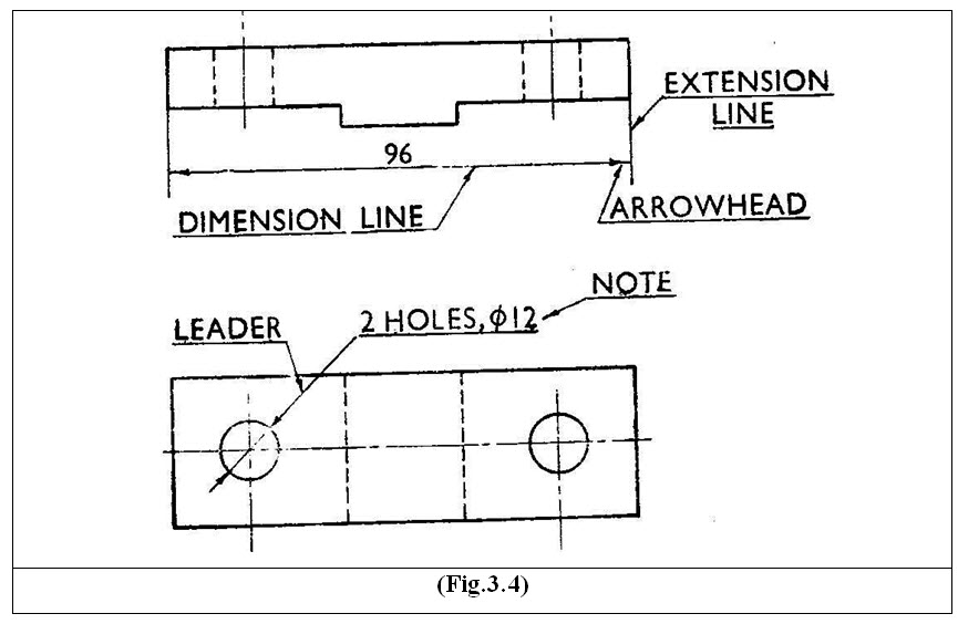
Extension lines: This is a line which are drawn to show the continuation of the edge or visible outline line of the object. These are lighter in weight and are drawn with a small gap next to the object line.
Dimension lines: These lines are drawn to show the dimensions of the object and are parallel to the object outline. These lines are drawn in between the extension lines having arrow heads at the beginning and end of the line.
Centre lines: These lines are drawn to represent the central axis or axes of a cylindrical or circular object. These are drawn with broken liens with a point in between the broken lines.
Hidden lines: The hidden corners which will not be visible in a particular view, are shown by broken lines.
Leader: The leader is a line with arrow head, drawn at an angle of not less than 30° to the line to which it touches. It gives information about a particular feature. The other end of the leader ends in a straight line which is at the bottom level of the note. The leader is never drawn vertical or horizontal. When a leader is directed towards a circle or an arc, it should be radial.
( To show the different lines in Computer aided drawing, different colours in different layers may be used.
The object is to be drawn in one layer
The extension lines in another layer
The dimensions in another layer
Centre lines and hidden lines may be drawn in another layer.)
3.2.3.Methods of Dimensioning
3.2.3.1.Unidirectional system
In this system, all the dimensions are placed by breaking the dimension lines in the middle, so that they can be read from the bottom edge of the drawing. This system is mainly used in large drawings.
3.2.3.2.Aligned system
In this system, the dimension is placed without breaking the dimension lines, in the middle and above the dimension line. The dimensions can be read from the bottom edge or the right hand side of the drawing.
Aligned system Unidirectional system
(Fig.3.5)
3.2.4.Arrangement of Dimensions
Dimensions in a view may be arranged or placed in any one of the following ways:
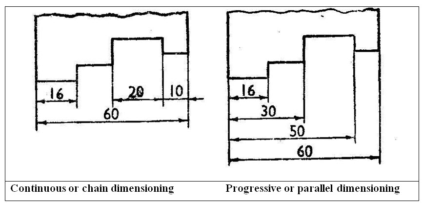
3.2.4.1.Progressive or parallel dimensioning
In this method, all the dimensions are shown from a common reference line. The cumulative error may be avoided from this method.
Here, the smaller dimensions must be placed nearer the object outline and the larger dimension should move away from the outline, so that the dimension lines do not cross the extension lines from the object. Extension lines may cross each other.
3.2.4.2.Continuous or Chain dimensioning
In this method, all the dimensions on one side of the object are aligned in a straight line.
An overall dimension is placed outside the smaller dimensions. These are accumulative dimensions.
(Fig.3.6.)
3.2.5.General laws
IS: 10718 – 1983 (Method of Dimensioning ) adopted from ISO/DIS : 129 specifies the methods and principles of dimensioning on engineering drawing.
The following points are to be taken care of while dimensioning.
Dimension lines should be at least 8 mm away from the outlines of the objects and from each other.
All dimensions should be done in detail so that further calculation or assumption of any dimension is not needed.
Any dimension should not be repeated unless it is unavoidable.
Dimensioning should be between the visible outlines. Dimensioning should not be between hidden lines.
Dimensions should be placed outside the view.
Dimensions should be given in the view (Top view, Front view or side view)
where it is shown more clearly.
Same dimension need not be repeated in each view.
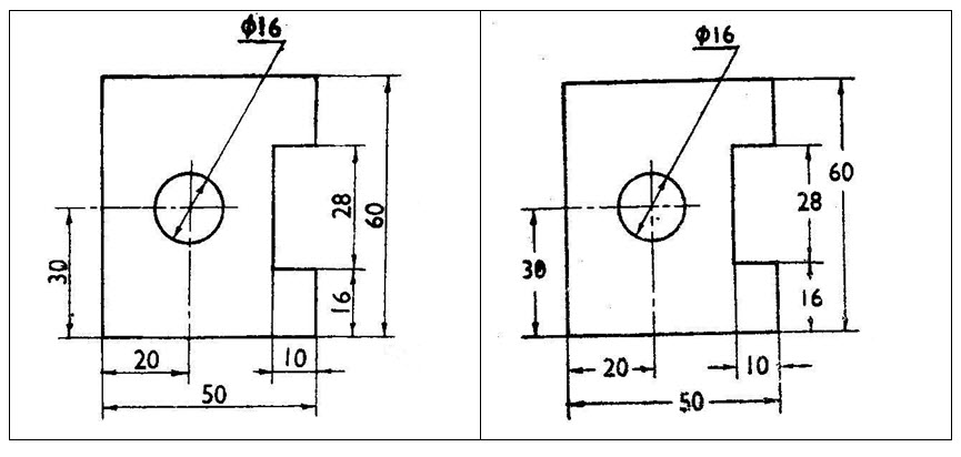
Dimensioning from the centre line should be avoided. But, features like hole or slot is specified by dimensioning from a visible outline or a reference (datum line).
Dimensioning of cylindrical parts should be placed in the views where they are seen as rectangles. The dimension of a cylinder should not be given as radius.
Dimensions of a hole or circle are to be specified by putting a ‘Φ’ symbol before the numerical value. Hole should be dimensioned in the view where they appear as circles.
The shape of a component is identified by inserting a suitable sign preceding the dimension number.
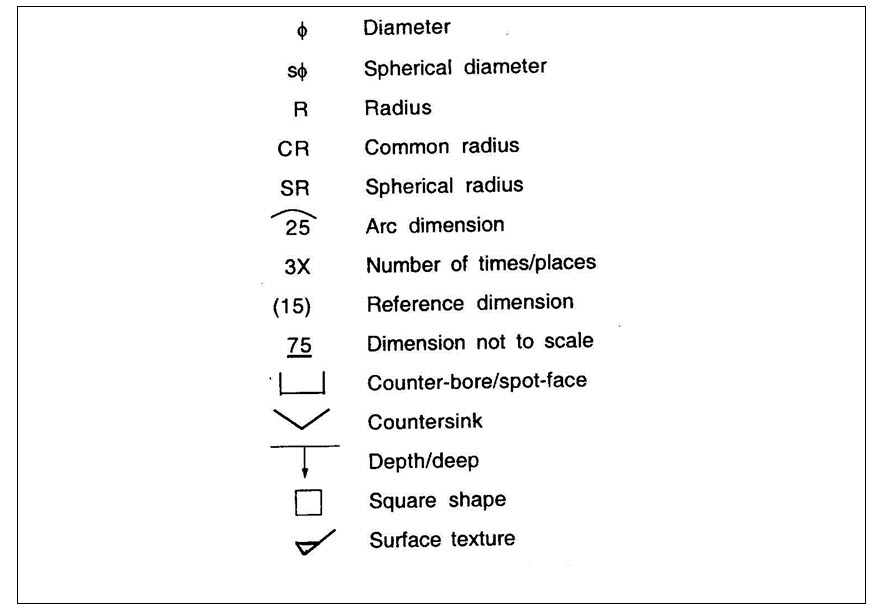
(Fig.3.7. Dimensioning symbols)
3.2.6.Unit of dimensioning
All the dimensions in a drawing should be expressed in one unit only. The B.I.S recommended unit is mm and only the number is given omitting the abbreviation ‘mm’. A foot note has to be given in the title block as “all the dimensions are in mm”. The height of the dimension figures should be 3 to 5 mm. when the dimension is less than unity, a zero must always precede the decimal point.
Last modified: Monday, 16 September 2013, 5:26 AM