Site pages
Current course
Participants
General
MODULE 1. Orhtographic Projections of Machine comp...
MODULE 2. Types of joints
MODULE 3. Computer Aided drawing
MODULE 4. Numeric control systems
Topic 5
Topic 6
Topic 7
Topic 8
Topic 9
Topic 10
LESSON 4. Concept of sections, revolved and oblique sections
4.1.Introduction
An orthographic projection of an object gives the external shape and details of the object clearly. We know that the invisible features of the object are shown in the projected view by means of hidden lines. When the invisible features are too many or of complex in nature, the hidden lines will be more and it makes the projection very difficult to understand. To overcome this difficulty, it is imagined that the object is being cut through or sectioned by a plane partially or completely and at the portion of the object between the cutting plane and the observer is assumed to be removed and the section so expressed is drawn to show the invisible and interior details of the object clearly. The view obtained is known as sectional view. The imaginary plane is known as cutting plane or sectional plane.
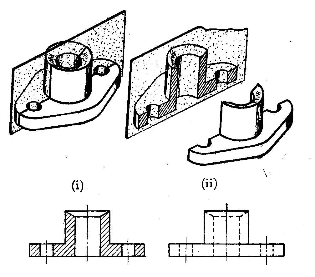
(Fig.4.1.Sectional view)
Revolved section
When a drawing has may numbers of long structural members of different cross sections, it is very difficult to identify the cross section of the member. In a particular view, a rectangular and circular duct may look alike. In such cases, the cross section of each member is shown by revolved section. A section is formed by passing a cutting plane at right angle to the axis of the object. This will be the actual cross section of the object. This section in a plane that is perpendicular to the plane of axis, is then revolved and brought in to the plane of the axis and placed in the view in which the axis is seen as a line. This section shown by a thin continuous line is known as revolved section.
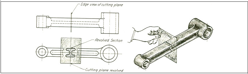
(Fig.4.2.Revolved section)
Removed section
This section is same as that of revolved section, but it is drawn outside the outline of the view.
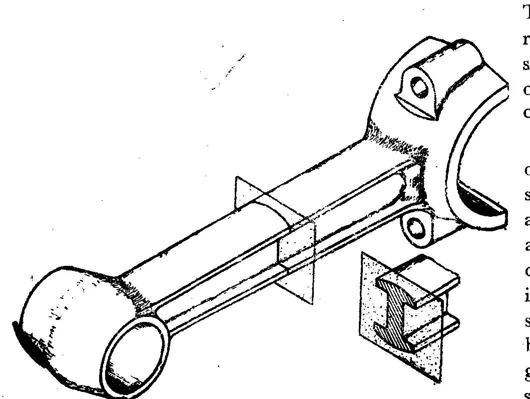
(Fig.4.3.Removed section)
Oblique section
In a mechanical drawing, a section taken through an object at an angle (other than 90°) to its longest axis is known as Oblique section. The section in the Oblique projection is termed as oblique section as shown in the figure.
(Fig4.4. Oblique section)
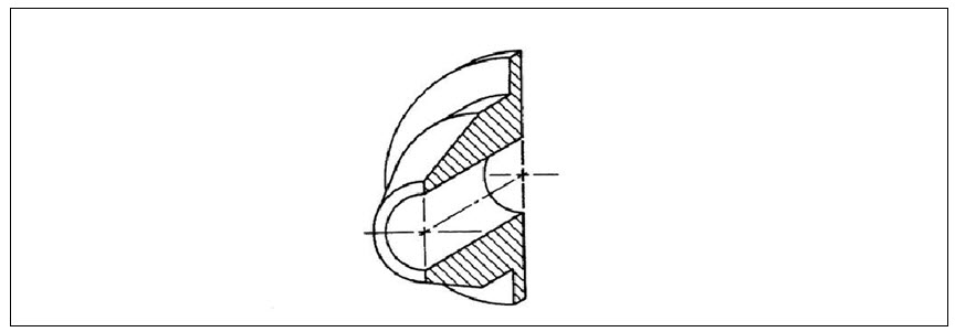
Half section
Any symmetrical object may be shown by this type of section. Here the object is cut by two cutting planes at right angles to each other and containing the two centre lines of the object. The one quarter portion of the object is assumed to be removed showing only half of the object’s inner details. The projected view is a half sectional view.
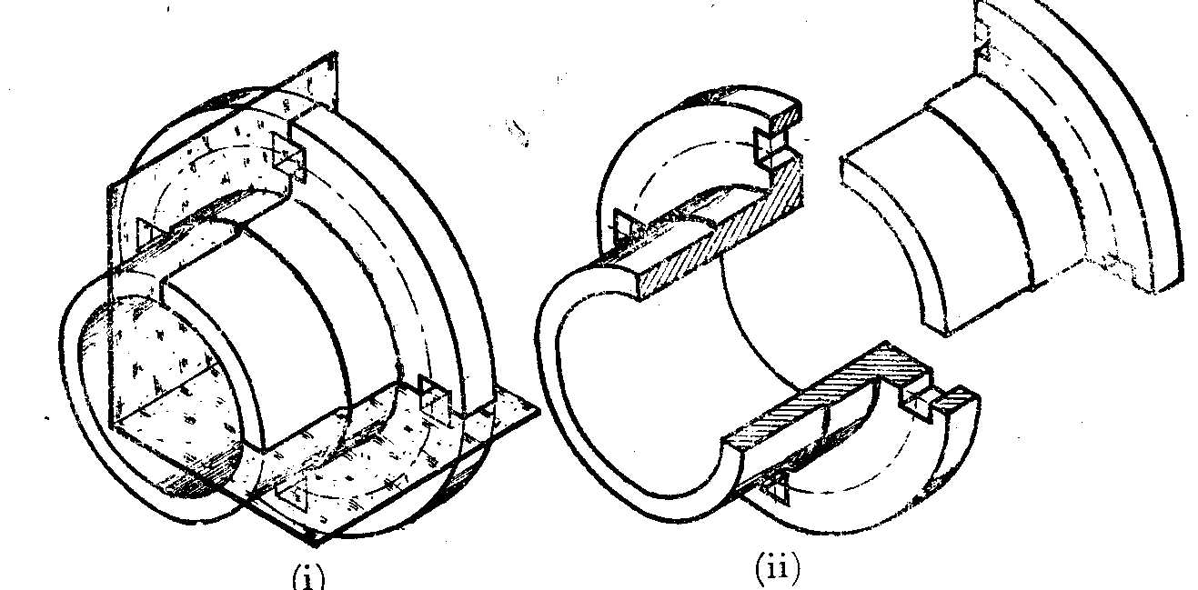
(Fig4.5. Half section)
Off set section
In order to obtain more details of the object, the cutting plane may be assumed to be offset as shown in the figure. The section thus obtained is known as Offset section. The position of the offset cutting plane is always shown by a cutting plane line in the view in which it is seen edgewise.
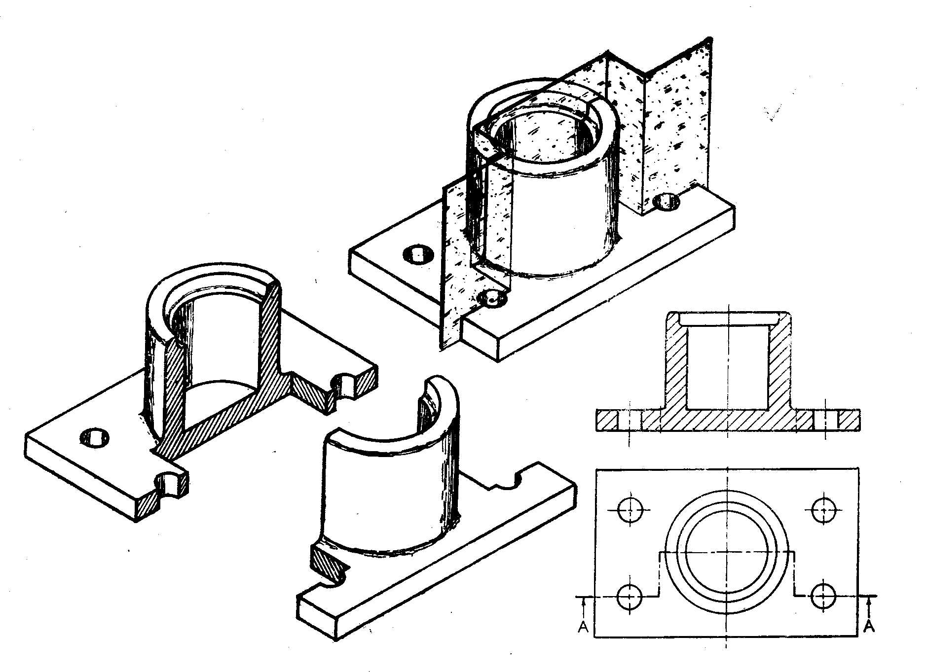
(Fig4.6. Offset section)
Sectioning conventions
When the cutting plane passes through the axes of bolts, nuts, studs, rivets, keys, cotters, shafts etc., they are not shown in section longitudinally.
They are shown when the cutting plane is at right angles to their axes i.e., shown in cross section. Similarly, the rib or web is not sectioned when the cutting plane cuts it along its length and breadth.
Objects of long lengths like shafts and pipes are shown by breaking in the middle.
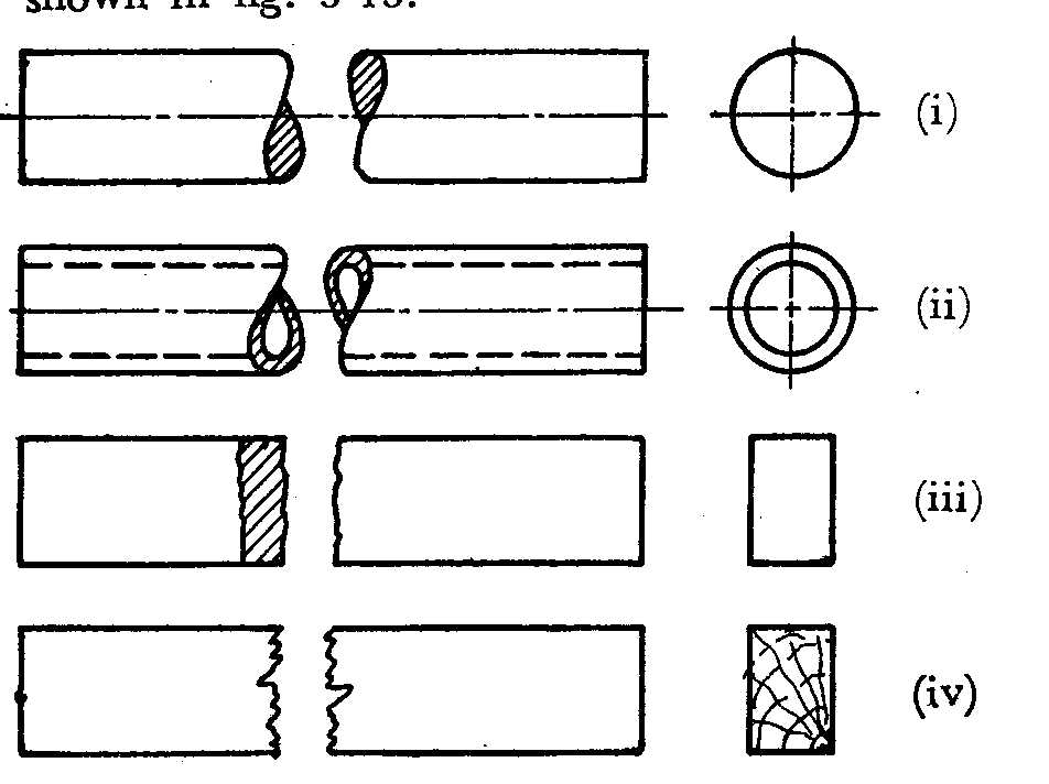
(Fig.4.7. Objects of long length)
Hatching of section lines
A section is differentiated from the object outline by hatching the sectioned portion by thin continuous lines drawn inclined at 45º to the axis or to the main outline. They should be placed equally, spacing varying from 1.5 to 3.5 mm. In computer aided drawing, many types of default section lines are available.
Last modified: Monday, 16 September 2013, 5:42 AM