Site pages
Current course
Participants
General
MODULE 1. Electro motive force, reluctance, laws o...
MODULE 2. Hysteresis and eddy current losses
MODULE 3. Transformer: principle of working, const...
MODULE 4. EMF equation, phase diagram on load, lea...
MODULE 5. Power and energy efficiency, open circui...
MODULE 6. Operation and performance of DC machine ...
MODULE 7. EMF and torque equations, armature react...
MODULE 8. DC motor characteristics, starting of sh...
MODULE 9. Polyphase systems, generation - three ph...
MODULE 10. Polyphase induction motor: construction...
MODULE 11. Phase diagram, effect of rotor resistan...
MODULE 12. Single phase induction motor: double fi...
MODULE 13. Disadvantage of low power factor and po...
MODULE 14. Various methods of single and three pha...
LESSON 8. Transformers on load
Practical transformer
Winding resistance
Flux leakage
Finite permeability
Core losses
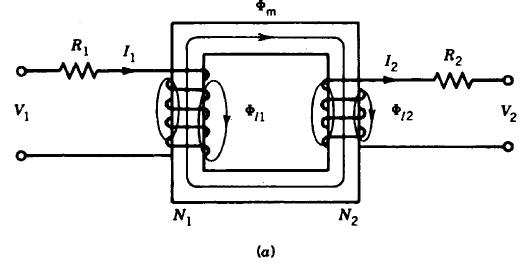
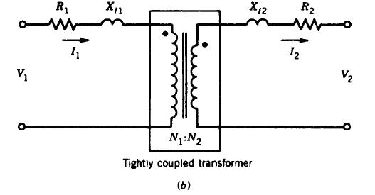
Fig. 4.4 Model of practical transformer
Transformer model
physical reasoning
mathematic model of coupled circuits
Winding resistance in series with leakage inductance
Magnetizing inductance in parallel with core resistance
Referred equivalent circuits
-
Practical transformer is equivalent to lumped parameters circuit and ideal transformer
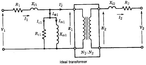
Fig. 4.5 Equivalent circuit of ideal transformer
The ideal transformer can be shifted to either side as in Figure 4.6 below and the circuit parameters reduce to the appropriate values
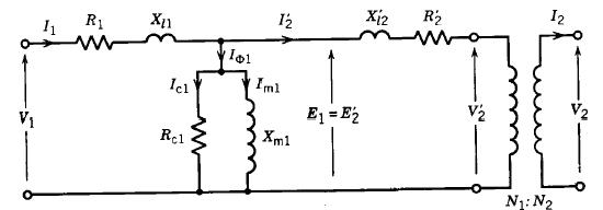
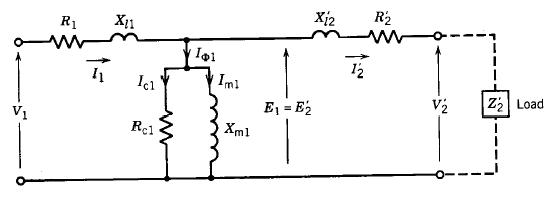
Fig. 4.6 Reduction of parameter in equivalent circuit
E1=E’2= aE2
V’2=aV2
I’2=I2/a
X’12=a2x12
R’2=a2R2
Approximate equivalent circuits
I1R1 and I1Xl1 are small Therefore, |E1| = |V1|
Shunt branch can be moved to supply terminal
IΦ small (5% of rated current) Shunt branch removed
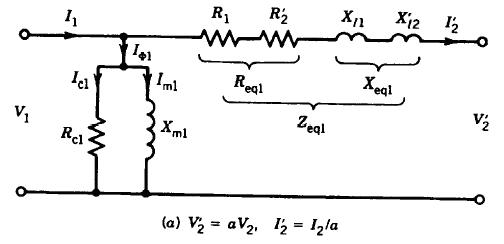
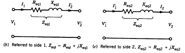
Fig. 4.7. Approximate equivalent parameters
Determination of equivalent circuit parameters
-
No-load test (rated voltage on one side whereas the other side is open)
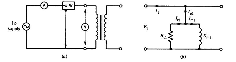
Fig. 4.8. Equivalent circuit parameters under no load test