Site pages
Current course
Participants
General
MODULE 1. Electro motive force, reluctance, laws o...
MODULE 2. Hysteresis and eddy current losses
MODULE 3. Transformer: principle of working, const...
MODULE 4. EMF equation, phase diagram on load, lea...
MODULE 5. Power and energy efficiency, open circui...
MODULE 6. Operation and performance of DC machine ...
MODULE 7. EMF and torque equations, armature react...
MODULE 8. DC motor characteristics, starting of sh...
MODULE 9. Polyphase systems, generation - three ph...
MODULE 10. Polyphase induction motor: construction...
MODULE 11. Phase diagram, effect of rotor resistan...
MODULE 12. Single phase induction motor: double fi...
MODULE 13. Disadvantage of low power factor and po...
MODULE 14. Various methods of single and three pha...
LESSON 9. Equivalent circuit and voltage regulation of transformers
intro
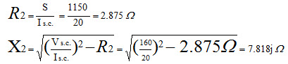
Short-circuit test (rated current on one side whereas the other side is short-circuited)
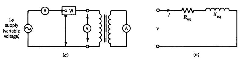
Fig. 4.9 Equivalent circuit parameters under short circuit test
Example
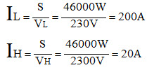
An Engineer needs to know the parameters of a 46KVA Transformer which has a 2300V/230V winding. His results are:
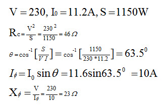
Open circuit test: 230V 11.2A 1150W
Short circuit test: 160V 28.0A 1150W
We must first determine which side low or high the test was performed on.
For the open circuit test we compare the tested voltage to the rated voltage of the transformer.
In this example we see that the open circuit test voltage is the same as the Low side rated operating voltage, thus we know the test was performed on the low side and the high side was left open.
Next we need to determine which side the short circuit test was performed on, so we compare the current this time.
Open circuit test: 230V 11.2A 1150W -H.V. Left open, and tested on low side
Short circuit test: 160V 28.0A 1150W -L.V. Shorted, and tested on high side
So we know that the Open Circuit parameters are referred to primary.
So we will use the referred to primary parameters for the open circuit test.
What we know:
-
This means our equivalent calculations are referred to the H.V. side. So in effect what we are calculating are our X2 and R2 values. If we want our X1 and R1 values, we must divide by our transformation ratio.
-
To complete our primary referred circuit we must find our R1 and X1 values. And given the fact that the transformer is stepping up voltage from 230 to 2300, we can see that it is a 1:10 ratio, or N1 = 1, N2 = 10.
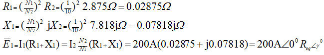
-
Now here we must convert our resistance into a singular vector for multiplication.
-
We will momentarily ignore our j operator to get the magnitude of the vector
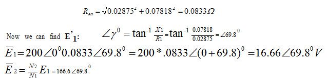
So you can see from the determination that 6.6 volts are due to internal losses in the transformer itself. Knowing this magnitude, an engineer can design a simulation with a source to the exact specifications and losses.
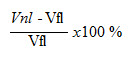
Voltage regulation
No load V2=V1/a
Loaded V2=V1/a ± ∆V2
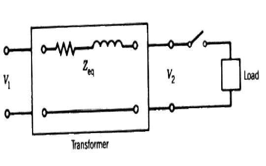
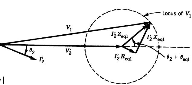
Fig. 4.10 Voltage regulation
Voltage regulation =