Site pages
Current course
Participants
General
MODULE 1. Electro motive force, reluctance, laws o...
MODULE 2. Hysteresis and eddy current losses
MODULE 3. Transformer: principle of working, const...
MODULE 4. EMF equation, phase diagram on load, lea...
MODULE 5. Power and energy efficiency, open circui...
MODULE 6. Operation and performance of DC machine ...
MODULE 7. EMF and torque equations, armature react...
MODULE 8. DC motor characteristics, starting of sh...
MODULE 9. Polyphase systems, generation - three ph...
MODULE 10. Polyphase induction motor: construction...
MODULE 11. Phase diagram, effect of rotor resistan...
MODULE 12. Single phase induction motor: double fi...
MODULE 13. Disadvantage of low power factor and po...
MODULE 14. Various methods of single and three pha...
LESSON 16. DC motors
THE MOTOR
A generator is a machine for converting mechanical energy into electrical energy and the motor is a machine for converting electrical energy into mechanical energy. The same machine however, may be used either as a motor or as a generator.
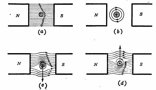
Fig. 8. 1 Force acting on a conductor carrying current in a magnetic field.
Fig. 8.1 (a) above shows a magnetic field of constant strength in which is placed a conductor that carries no current. In Fig. 8. 1 (b) the conductor is shown as carrying a current into the paper, but the field due to the N and S poles has been removed. A cylindrical magnetic field now exists about the conductor due to the current in it (R.H cork screw rule). Figure Fig. 8. 1 (c) shows the resultant field obtained by combining the main field and that due to the current. The field due to the current in the conductor acts in conjunction with the main field above the conductor, whereas it opposes the main field below the conductor. The result is to crowd the flux above the conductor and to reduce the flux density in the region below the conductor. It will be found that a force acts on the conductor, trying to push the conductor down, as shown by the arrow. If the current in the conductor is reversed, the force will tend to move it upward, as shown in Fig. 8. 1 (d). The electric motor works upon this fact that a conductor carrying current in a magnetic field tends to move at right angles to the field.
Force Developed with Conductor Carrying Current.— The force acting on a conductor is expressed as,
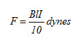
Where, B is the flux density in lines per cm2 (gauss), l the active length of the conductor in cm and I the current in amperes.
Fleming's Left hand Rule (Fig. 8. 2) gives the relation between the direction of a magnetic field, the direction of a current in that field and the direction of the resulting motion of the conductor.
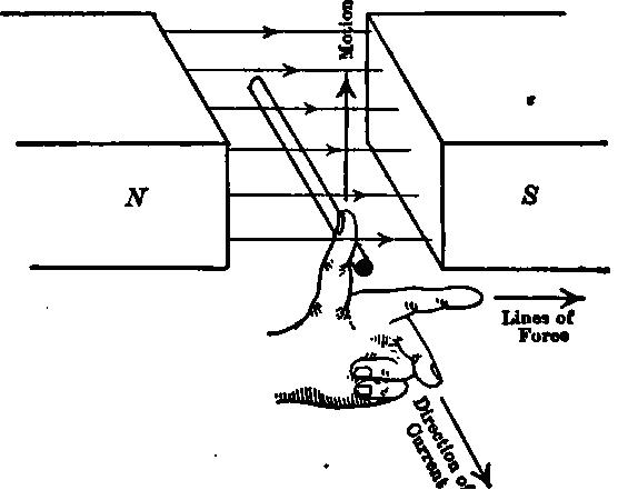
Fig. 8. 2 Fleming's left-hand rule.
“Point the forefinger in the direction of the field or flux, the middle finger in the direction of the current in the conductor, and the thumb will point in the direction in which the conductor tends to move.”
Example. A coil consisting of 20 turns lies with its plane parallel to a magnetic field, the flux density in the field being 3,000 lines per cm2. The axial length of the coil is 8 inch. The current per conductor is 30 A. Determine the force which acts on each side of the coil.
B = 3,000
l = 8 × 2.54 = 20.32 cm.
I = 30 A
F1 = 3,000 × 20.32 × 30/10 = 182,900 dynes.
As there are 20 turns
F = 20 × 182,900 = 3,658,000 dynes.
Torque: When an armature, a fly wheel or any other device is revolving about its center, a tangential force (Fig. 8. 3) is necessary to produce and maintain rotation. This force may be developed within the machine itself as in a motor or steam engine, or it may be applied to a driven device such as
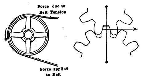
Fig. 8. 3 Torque developed by a belt and by gears.
a pulley, a shaft, a generator, the driving gears on the wheels of car, etc. The product of this force and its perpendicular distance from the axis is called torque. Torque is a mechanical couple tending to produce rotation. In the SI, unit of torque is the Nm and in the metric system the unit is the kilogramforce-meter.