Site pages
Current course
Participants
General
MODULE 1. Electro motive force, reluctance, laws o...
MODULE 2. Hysteresis and eddy current losses
MODULE 3. Transformer: principle of working, const...
MODULE 4. EMF equation, phase diagram on load, lea...
MODULE 5. Power and energy efficiency, open circui...
MODULE 6. Operation and performance of DC machine ...
MODULE 7. EMF and torque equations, armature react...
MODULE 8. DC motor characteristics, starting of sh...
MODULE 9. Polyphase systems, generation - three ph...
MODULE 10. Polyphase induction motor: construction...
MODULE 11. Phase diagram, effect of rotor resistan...
MODULE 12. Single phase induction motor: double fi...
MODULE 13. Disadvantage of low power factor and po...
MODULE 14. Various methods of single and three pha...
LESSON 20. DC compound motor characteristics and DC motor starters
The Compound Motor
A shunt motor if added with an additional series winding becomes a compound motor. This winding may be connected to aid the shunt winding, in which case the motor is said to be cumulative compound; or the series winding may oppose the shunt winding, in which case the motor is said to be differential compound. The characteristics of the cumulative compound motor are a combination of the shunt and series characteristics. As the load is applied the series turns increase the flux, causing the torque for any given current to be greater than it would be for the simple shunt motor.
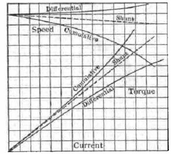
Fig. 8.11 Torque and speed characteristics of shunt and compound motors
On the other hand, this increase of flux causes the speed to decrease more rapidly than it does in the shunt motor. These characteristics are shown in the figure 8.11. The cumulative compound motor develops a high torque with sudden increase of load. It also has a definite no-load speed, so does not run away when the load is removed.
Its field of application lies principally in driving machines which are subject to sudden applications of heavy load, such as in rolling mills, shears, punches, etc. This type of motor is used also where a large starting torque is desirable but where a straight series motor cannot be conveniently used. Cranes and elevators are representative of such loads.
In the differential compound motor, the series field opposes the shunt field so that the flux is decreased as the load is applied. This results in the speed remaining substantially constant or even increasing with increase of load. This speed characteristic is obtained with a corresponding decrease in the rate at which the torque increases with load. Such motors are used where a very constant speed is desired. Because of the substantially constant speed of the shunt motor there is little occasion to use the differential motor. In starting a differential compound motor the series field should be short-circuited, as the large starting current passing through the series field may be sufficiently large to overbalance the shunt field ampere-turns and cause the motor to start in the wrong direction.
To reverse the direction of rotation in any DC motor, either the armature alone or the field alone must be reversed. If both are reversed the direction of rotation remains unchanged.
DC Motor Starters
It was shown that if a 10-hp 220 volt DC motor were connected directly across DC mains, the resulting current (since there wont be back emf at staring time) would be 4400 A. Such a current would not be permissible and hence, resistance should be connected in series with the motor armature when starting. This resistance may be gradually cut out as the armature comes up to speed and develops a back electromotive force. Figure 8.12 shows the use of a simple resistance R for starting a motor. It will be noted that this resistance is in the armature circuit and that the field is connected directly across the line and outside the resistance. If the field were connected across the armature terminals, putting the resistance R in series with the whole motor, there would be little or no voltage across the field. There would be little torque developed and difficulty in starting would be experienced.
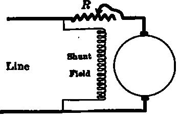
Fig. 8.12 Resistance used for starting purposes
Figure 8.13 shows a 3-point starter, which does not differ fundamentally from the connections shown above. One line connects directly to an armature and a field terminal tied together. It makes no connection whatever with the starter. The other line goes to the line terminal of the starter which is connected directly to the starting arm. The starting arm moves over contacts set in the insulator front board of the starter. These contacts connect with taps distributed along the starting resistance. The armature terminal of the starting box, which is the right-hand end of the starting resistance, is connected to the other armature terminal of the motor. The field connection in the starter is connected from the first starting contact, through the hold up magnet, to the field terminal of the box. This field terminal is connected directly to the other terminal of the shunt field. When the starting arm makes connection with the first contact, the field is put directly across the line and at the same time all the starting resistance is in series with the armature. As this arm is moved slowly, the starting resistance is gradually cut out. When the arm reaches the running position, the starting resistance is all cut out. The field current now feeds back through the starting resistance. This resistance is so low compared with the resistance of the field itself that it has no material effect upon the value of the field current. A spring tends to pull the starting arm back to the starting position.
When the arm reaches the running position, it is held against the action of this spring by a soft-iron magnet (hold-up magnet), connected in series with the shunt field. (A soft-iron armature is often attached to the starting arm as shown in the figure.) If for any reason the line has no voltage, the starting arm will spring back to the starting position. Otherwise, if the voltage again came on the line after a temporary shut-down, the stationary motor armature would be thrown directly across the line and a short-circuit would result.
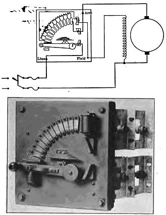
Fig. 8.13 Three point DC motor starter