Site pages
Current course
Participants
General
MODULE 1. Electro motive force, reluctance, laws o...
MODULE 2. Hysteresis and eddy current losses
MODULE 3. Transformer: principle of working, const...
MODULE 4. EMF equation, phase diagram on load, lea...
MODULE 5. Power and energy efficiency, open circui...
MODULE 6. Operation and performance of DC machine ...
MODULE 7. EMF and torque equations, armature react...
MODULE 8. DC motor characteristics, starting of sh...
MODULE 9. Polyphase systems, generation - three ph...
MODULE 10. Polyphase induction motor: construction...
MODULE 11. Phase diagram, effect of rotor resistan...
MODULE 12. Single phase induction motor: double fi...
MODULE 13. Disadvantage of low power factor and po...
MODULE 14. Various methods of single and three pha...
LESSON 27. Single phase motor – series motor
Series Motor.
It will be remembered that the direction of rotation of either the direct current shunt motor or the direct current series motor is the same irrespective of the polarity of the line voltage. If the line terminals be reversed, both the field current and the armature current are reversed and the direction of rotation remains unchanged. If such motors be supplied with alternating current, the net torque developed acts in one direction only.
With alternating current, the shunt motor develops but little torque. The high inductance of the shunt field causes the field current and therefore the main flux to lag nearly 90° in time phase with respect to the line voltage. The armature current cannot lag the line voltage by a large angle if the motor is to operate at a reasonable power factor. Therefore, there will be considerable phase difference between the main flux and the armature current. Consequently, such a motor will develop but little torque per ampere. This particular type of alternating current shunt motor is therefore not practicable.
In the series motor (Fig. 12.1), the armature current and the field current are in phase with each other. The main flux is practically in phase with the field current. Therefore, the armature current is substantially in phase with the flux, and the torque curve has no negative loops. Consequently, the series motor develops approximately the same torque per ampere with alternating current as it does with direct current. Fundamentally, the series motor has possibilities as an alternating current motor.
The ordinary direct current series motor does not operate satisfactorily with alternating current for the following reasons:
(a) The alternating field flux sets up eddy currents in the solid parts of the field structure, such as the yoke, cores, etc., causing excessive heating and a lowering of efficiency,
In the alternating current series motor this difficulty is eliminated by laminating the field structure. Even with laminated field cores, however, losses in the iron occur with alternating current which do not occur with direct current.
(b) There is a relatively large voltage drop across the series fields, due to their high reactance. This limits the current and also reduces the output and power factor to such low values as to make the motor impracticable.
In the alternating current motor this difficulty is partially overcome as follows:
A low frequency is used, since reactance, X, is 2r/L, where / is the frequency and L the inductance. Even when the field
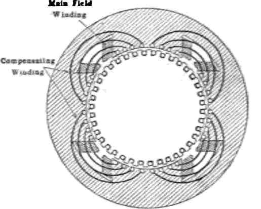
Fig. 12.1 Windings of an alternating current series motor.
inductance, L, is made as low as is practicable, the field reactance, X, will be considerably too high unless the frequency/is made low. The usual lighting frequency of 50 cycles is much too high, except for motors of fractional horsepower rating. Difficulty is experienced in designing a series motor for a frequency of 25 cycles, even. To obtain satisfactory operation, frequencies of 12 and 15 cycles are commonly used for this type of motor.
(c) The armature of an alternating current series motor of a given rating has an unusually large number of conductors. A motor of fixed horsepower and speed must develop a corresponding torque. The torque developed by a motor is proportional to the product of the field flux and the armature ampere conductors. Therefore, if the total flux of the alternating current motor is less than the total flux of a direct current motor of the same rating, the armature ampere conductors of the alternating current motor must be correspondingly increased in order to obtain the required torque. This is one reason why the armature of the alternating current motor is larger than that of the direct current motor of the same rating.
(d) The alternating current motor has a lesser number of field ampere turns and a greater number of armature ampere turns than the corresponding direct current motor. That is, the motor has a strong armature and a weak field. This means that the armature reaction is unduly large. Therefore, the effect of the armature cross magnetizing turns, unless compensated, is to produce unusually great field distortion. As this distortion of the field by the cross magnetizing armature ampere turns would make commutation practically impossible, this cross magnetizing action must be neutralized. This is accomplished by means of a compensating winding placed between the main poles, this winding being embedded in the pole faces.
(e) In the allernating current series motor a commutating difficulty occurs which is not present in the direct current motor.
The single phase series motor has practically the same operating characteristics as the direct current series motor. This is illustrated below (Fig. 12.2), which gives the operating characteristics of a typical railway motor. The torque or tractive effort varies nearly as the square of the current and the speed varies inversely as the current, or nearly so. If conductively compensated, the motor operates satisfactorily with direct current and at increased output and efficiency. When the motor is operated with alternating current, the speed may be efficiently controlled by taps on a transformer. This efficient speed control is not possible with direct current.
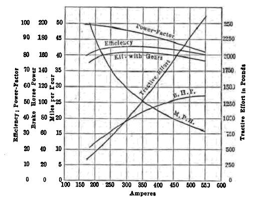
Fig. 12.2 Characteristic curves of a series motor