Site pages
Current course
Participants
General
MODULE 1. Electro motive force, reluctance, laws o...
MODULE 2. Hysteresis and eddy current losses
MODULE 3. Transformer: principle of working, const...
MODULE 4. EMF equation, phase diagram on load, lea...
MODULE 5. Power and energy efficiency, open circui...
MODULE 6. Operation and performance of DC machine ...
MODULE 7. EMF and torque equations, armature react...
MODULE 8. DC motor characteristics, starting of sh...
MODULE 9. Polyphase systems, generation - three ph...
MODULE 10. Polyphase induction motor: construction...
MODULE 11. Phase diagram, effect of rotor resistan...
MODULE 12. Single phase induction motor: double fi...
MODULE 13. Disadvantage of low power factor and po...
MODULE 14. Various methods of single and three pha...
LESSON 29. Single phase induction motor - double field revolving theory
Single phase Induction Motor
Figure 12.6 shows a two pole motor whose magnetic field is produced by single phase current flowing in a simple field winding.
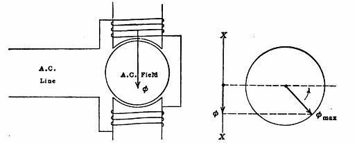
Fig. 12.6 Single phase, alternating field and the Time variation of the AC field.
The current in this field is assumed to vary sinusoidally with time and if the iron be assumed to operate at moderate flux densities, the flux through the armature will vary practically sinusoidally with time. The variation of this field with time may be represented (Fig. 12.6) by the projection of a rotating vector φmax upon a vertical axis XX shown. The vector φmax is equal to the maximum value of the flux and its speed of rotation in revolutions per second is equal to the line frequency in cycles per second.
It may also be assumed that this single phase field is made up of two equal and oppositely rotating fields represented by two equal and oppositely rotating vectors as shown in Fig. 12.7 (a), the maximum value of each of these fields or vectors being equal to one half of jmax. The resultant of two such vectors always lies along the vertical axis and is equal in magnitude at any instant to the field actually existing at that instant.
The same thing is represented in Fig 12.7(b), which shows the flux distribution curves of two fields j1 and j2, each of which is equal to one half the maximum field. These two fields glide around the air gap in opposite directions and with equal velocities.
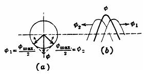
Fig. 12.7 Single phase field as split fields.
Their algebraic sum j at any instant is the value of the resultant field at that instant and this resultant field is stationary in space.The single phase field may be considered therefore as made up of two equal rotating fields, revolving in opposite directions. (Experiment shows that two such fields actually exist.) Each field acts independently upon the rotor and in the same manner as the rotating field of the polyphase induction motor. One field tends to cause rotation in a clockwise direction and the other field tends to cause rotation in a counter clockwise direction. Figure 12.8 shows the slip torque curve due to each of the two fields.
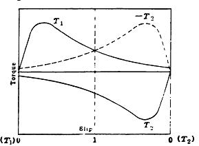
Fig. 12.8 Two opposing torques in a single phase induction motor
The torques act in opposite directions as shown. At standstill (slip = 1) the two torques are opposite and equal, and the rotor has no tendency to start. If the rotor in some manner be caused to rotate in the direction in which the torque T1\ is acting, T1\ will immediately exceed the counter torque T2 and armature will begin to accelerate in the direction of T1. As the armature speeds up, T1 predominates more and more over T2 and the armature approaches synchronous speed without difficulty. The counter torque due to T2 always exists, however, although it has little effect near the synchronous speed of the field which produces T1.
When the rotor operates near synchronous speed and rotates in the direction of T1, its slip is nearly two as regards T2. Therefore, the rotating field which produces T1 induces double frequency currents in the rotor at this speed. These double frequency currents, however, produce but little torque because of their high frequency. This frequency is double the stator frequency. Therefore, the rotor reactance is many times its value at slip frequency. Consequently, these currents are small in magnitude and make a considerable space angle with the air gap flux, developing little counter torque.
It is obvious that the single phase induction motor rotates in the direction in which it is started.
Starting Single phase Induction Motors.
As the single phase induction motor is not self starting, auxiliary means must be used to supply initial torque. One method is to split the phase by the use of inductance, resistance or capacitance.
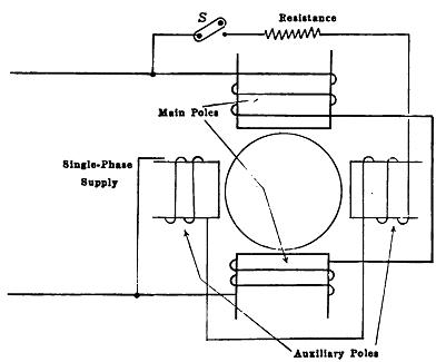
Fig. 12.9 Starting Single phase Induction Motors
Figure 12.9 shows one method of splitting the phase, a two pole motor being shown. The main winding, which is highly inductive, is connected across the line in the usual manner. Between the main poles are auxiliary poles which have a high resistance winding and this winding is also connected across the line. As the auxiliary winding has a high resistance, its current will be more nearly in phase with the voltage than the current in the main winding. For the best conditions, the two currents should differ in phase by 90°, but this condition is not readily obtainable, and in fact is not necessary. These two sets of poles produce a sort of rotating field which starts the motor. When the motor comes up to speed, a centrifugal device in the rotor opens the switch ‘S’ and disconnects the auxiliary winding.
|
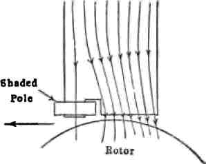
Fig. 12.10 Shaded pole method |
The shaded pole method is shown figure 12.10. A short circuited coil of low resistance is connected around one pole tip. When the flux is increasing in the pole, a portion of the flux attempts to pass down through this shaded tip. The flux induces a current in the coil which by Lenz's law is in such a direction as to oppose the flux entering the coil. Hence, at first the greater portion of the flux passes down the right hand side of the pole, as shown.
Ultimately, however, the main flux reaches its maximum value, where its rate of change is zero. The opposing emf in the shading coil then becomes zero, and later the opposing mmf of the short circuited coil ceases, the current in this coil lagging its emf. Considerable flux then penetrates the short circuited coil. After the main flux begins to decrease, the induced current in the shading coil tends to prevent the flux then existing in the shaded portion of the pole tip from decreasing. Therefore, the flux first reaches its maximum value at the right hand or non shaded side of the pole, and later reaches its maximum at the left hand or shaded side. The effect of the shading coil is to retard in time phase a portion of the flux, so that there is a sweeping of the flux across the pole face from the right hand to the left hand side in the direction of the shading coil. This flux cutting the rotor conductors induces currents, which in turn produce a torque sufficient to start the motor. The shaded pole is not a common method of starting single phase induction motors and is used only in motors of very small size.