Site pages
Current course
Participants
General
MODULE 1. Electro motive force, reluctance, laws o...
MODULE 2. Hysteresis and eddy current losses
MODULE 3. Transformer: principle of working, const...
MODULE 4. EMF equation, phase diagram on load, lea...
MODULE 5. Power and energy efficiency, open circui...
MODULE 6. Operation and performance of DC machine ...
MODULE 7. EMF and torque equations, armature react...
MODULE 8. DC motor characteristics, starting of sh...
MODULE 9. Polyphase systems, generation - three ph...
MODULE 10. Polyphase induction motor: construction...
MODULE 11. Phase diagram, effect of rotor resistan...
MODULE 12. Single phase induction motor: double fi...
MODULE 13. Disadvantage of low power factor and po...
MODULE 14. Various methods of single and three pha...
LESSON 28. Single phase motor – Repulsion motor
The Repulsion Motor
If an ordinary direct current armature be placed in a single phase magnetic field and the brushes be short circuited, a simple repulsion motor is obtained. In order to develop torque, however, the brush axis must be displaced from the axis of the main field by about 18 or 20 electrical space degrees, as will be shown.
The armature is same as the DC motor’s which operates in a bipolar magnetic field which is excited by a single phase AC supply voltage. At the instant shown in Fig. 12.3, upper line is positive and current increasing in positive direction. By corkscrew rule, the magnetic field is upward and increasing with current magnitude. This flux divides half going through each side of the shorted armature. Each side of armature hence acts as the secondary of a transformer.

Fig. 12.3 Currents in the windings of a repulsion motor (brushes in geometrical neutral).
Therefore, the alternating flux produced by the field winding, as primary, induces an emf in each half of the armature. By Lenz's law, this induced emf has such a direction as to oppose the inducing flux. The direction of this induced emf at the instant indicated in figure Fig. 12.3 (a) is given by the arrows on the windings. It will be noted, by following through the winding, that the resultant direction of this induced emf is upward on each side of the armature. Were there no brushes, it is evident that no current would flow in the armature winding, as the emf in one half of the winding is equal and in phase opposition to that in the other half. The brushes are shown as being in the geometrical neutral and short circuited. Each brush is at the mid point of its transformer winding. As the total emfs. in each winding are the same and the windings are connected in parallel, each midpoint must be at the same potential.
Therefore, the brushes short circuit two points at the same potential and no current flows between brushes. It is clear that without brushes there is no armature current, and even with brushes there is no armature current, provided the brush axis is at right angles to the pole axis. Therefore, under both these conditions there is no armature current and, hence, no torque.
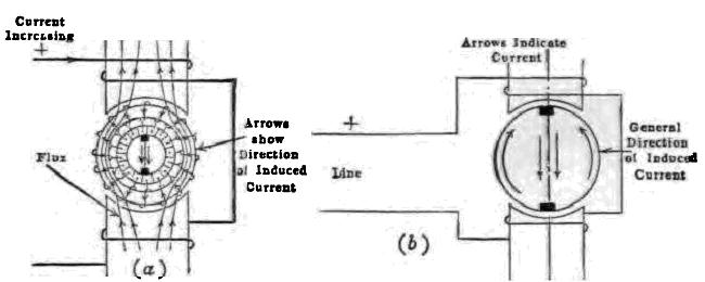
Fig. 12.4 Currents in the windings of a repulsion motor, brushes along pole axis
Figure 12.4 shows the same condition existing in the field and armature as before, except that the brushes now lie along the pole axis. As the general direction of the induced emfs have not changed, the brushes are now short circuiting the points of the armature winding across which the maximum potential difference exists. Therefore, current flows between the brushes from both sides of the armature, and in this brush position, the current in the armature is a maximum. But the motor develops no torque since two conditions are necessary for the development of torque.
(1) The angle between the space position of the flux axis and the brush axis must be greater than zero. For maximum torque this angle should be 90°. For example, in a direct current motor with fixed flux and armature current, the maximum torque occurs when the brushes are in the neutral plane, that is at right angles to the flux. No torque would be developed were the brush axis parallel to that of the flux.
(2) There must be a component of current in time phase with the flux. If there is 90° time lag between the current and the flux, the current is a maximum at the instant the flux is zero, etc., and the average torque is zero. With flux, armature current and brush position all fixed, the maximum torque occurs when the flux and armature current are in time phase with each other.
Under the conditions, the brush axis being parallel to the resultant flux, (the angle between the flux and the brush axis is zero), the current flows in opposite directions in the two equal conductor belts on each side of the brush axis. Hence in this type of motor, no torque is developed when the brush axis is at right angles to the flux, for then there is no current; no torque is developed when the brush axis is parallel to the flux, because the ampere conductors under each pole develop opposite and equal torques.
It is obvious, however, that if the brushes be placed in some intermediate position, they will be short circuiting points of the winding between which a difference of potential exists and therefore currents will flow in the winding, and also the net ampere conductors under each pole cannot be zero. It can also be shown that the armature current is substantially in time phase with the flux. Therefore, under these conditions, the motor develops torque.
Figure 12.4 (a) shows the brush axis making an angle a with the pole axis. The arrows in this figure show the direction of the armature current at the instant when the upper wire is positive and the current is increasing positively.
The figure 12.5 shows diagrammatically the general direction of these currents through the armature and brushes. It will be observed that the current direction in the conductors under each pole is such as to develop torque. Figure 12.5 (c) shows the direction of induced emf in the armature, neglecting the distorting effect of the armature mmf, on the field flux. The emfs in each half of the armature act in conjunction as shown Fig. 12.5 (b). Assume for the time being that angle b equals angle a in Fig. 12.5 (c). The current paths through the winding are abcd and afed. In path abcd, the emfs, Ecd and Ecb included in angles a and b respectively, each equal to the brush displacement angle, are equal and act in opposition. Therefore, they cancel each other, leaving Eab as the net emf through path abcd. Likewise in path afed, the emfs. Efa and Efa cancel, leaving Ead as the net emf through this path. The net emfs Eab and Ecd are effective in sending the current through the armature.
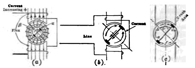
Fig. 12.5 Brush position in a repulsion motor which gives both current and torque
In this type of motor, the direction of rotation depends on the brush position. For example, the direction of rotation may be reversed by moving the brushes so that they cross the pole axis, the brush axis then making an angle b with the pole axis. Angle b must be less than 90°.
Instead of displacing the brushes from the geometrical neutral so that a potential difference exists between them, which results in a current, giving rise to torque, the same effect may be obtained by using two field windings displaced at right angles to each other. Practically all repulsion motors are made with non salient poles, rather than with the salient poles shown in the diagrammatic illustrations. The windings are usually of the distributed type, such as are used for induction motors. Repulsion motors have characteristics similar to those of series motors and have large starting torque. The sparking is very small at synchronous speed (3,600 rpm for a two pole, 50 cycle motor) but at speeds differing greatly from this, the sparking may be excessive. There are several types of repulsion motor on the market which, while differing in detail from the motor just described, involve identical principles.