Site pages
Current course
Participants
General
Module 1: Fundamentals of Reservoir and Farm Ponds
Module 2: Basic Design Aspect of Reservoir and Far...
Module 3: Seepage and Stability Analysis of Reserv...
Module 4: Construction of Reservoir and Farm Ponds
Module 5: Economic Analysis of Farm Pond and Reser...
Module 6: Miscellaneous Aspects on Reservoir and F...
Lesson 30 Method to Reduce Seepage and Evaporation Losses
30.1 Introduction
The water harvested in the reservoir and farm ponds is a very scarce resource. All care should be taken to prevent any kind of loss of this harvested water. Two major forms of losses of this water are (i) evaporation losses and (ii) seepage losses. Estimate of evaporation across the country indicates that it is as high as 2000 mm per annum in the semi-arid tropics. Annual average value of the evaporation loss varies from 1400 to 1800 mm across major parts of the country; the value being highest in west Rajasthan, parts of Saurasthtra and Tamilnadu and lowest in coastal Mysore, Bihar plateau and eastern Madhya Pradesh. Reliable statistics reveals that about 70 M ha m of water, out of the total annual precipitation of 400 M ha m, evaporates from the water bodies and land surfaces of the country.
In this section, the methods to estimate the losses like seepage and evaporation and various measures to control them are discussed.
30.2 Evaporation Losses in Farm Pond
Evaporation is the process by which water is converted from its liquid form to its vapor form and thus transferred from land and water masses to the atmosphere. It is a natural process and occurs when solar radiation falls on a water body. The solar energy thus transmitted is acquired by water molecules which in turn gets separated and move upward causing evaporation. In the hydrologic cycle, evaporation plays a vital role in causing precipitation. Thus, in one hand it is required for precipitation which in turn builds up the water resources and on the other hand it causes huge losses of the scarce harvested water from farm ponds and other reservoirs. Evaporation loss from the small and shallow ponds/reservoirs is higher than the large and deep reservoirs. Sometimes it may be as high as 50% of the capacity of the reservoir. Ambient temperature, relative humidity and wind velocity are the factors other than the cross sectional geometry of the water harvesting structures responsible for enhancing the rate of evaporation. Hence, it is higher in summer months during March and June; and lower in winter months during October and February. Again, it is more pronounced in arid climate than a humid climate. As the cost involvement is higher in construction of the storage structures, it becomes essential to minimize such losses from water bodies.
30.3 Estimation of Evaporation
Various methods are used to estimate the rate of evaporation. Some of them are discussed below.
30.3.1 Analytical Method
Analytical methods to estimate the rate of evaporation are divided into two types. They are (i) water budget method and (ii) mass transfer method.
Water Budget Method
Water budget method is based on water balance approach in which various inflows and outflows to and from the farm pond are considered. The equation used to evaluate evaporation is:
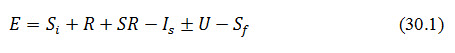
Where, E = evaporation, Si and Sf= Initial and final storage in the farm pond respectively; R = Rainfall; SR =Runoff/surface inflow; Is= supplemental irrigation/surface outflow; and U = Underground inflow or outflow into or from the reservoir. The various terms used in above equation are expressed in terms of depth unit, generally in cm.
Surface run off generated from the crop field/catchment at the upstream is directed into the pond. So, it increases during rainfall events and decreases during irrigation intervals.
Mass Transfer Method
Mass transfer is the net movement of mass from one point, here the pond surface, to another, the atmosphere. Mass transfer occurs in many processes, such as absorption, evaporation, adsorption, drying, precipitation etc. The phrase is commonly used in engineering for physical processes that involve diffusive and convective transport of chemical species within physical systems.
In this method, the rate of evaporation is computed as:
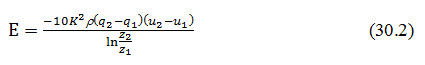
where, K= von Karman constant 0.41;= density of air, g/cc; q2 and q1 are specific humidity at heights Z2 and Z1, respectively that are taken as 2 m and 1m, respectively above the water surface; and u2 and u1 are wind speeds, cm/s at heights Z2 and Z1, respectively.
30.3.2 Empirical Method
There are several empirical methods developed for computing evaporation loss. Most of these methods take into account the evaporation loss of the farm pond which in turn depends on temperature of air water interface, wind velocity, relative humidity and saturated vapour pressure of air.
30.3.3 Energy Budget Method
In this method, the rate of evaporation is computed as:
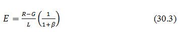
Where, R = H+ LE +G is given as:
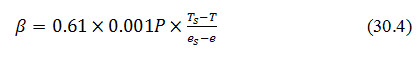
where, R = net radiation flux received at the surface, cal/cm2; H= sensible heat flux, cal/cm2; LE= latent heat flux (L= Latent heat of vapourisation, cal/g and E as defined above); G= heat flux in the soil or water, cal/cm2; = Bowen ratio; Ts= temperature of water surface(C); T= air temperature (C); es= saturation vapour pressure at Ts, hectopascal (hpa); e= vapour pressure of air at T, hpa; and P= station level pressure, hpa.
Based on Penman’s equation (1948), the Kohler-Nordenson-Fox equation describes evaporation from water bodies as the combination of water loss due to radiation heat energy and the aerodynamic removal of water vapor from a saturated surface.
The general form of the combination equation is described as:
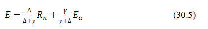
Where, Δ= slope of the saturation vapour pressure curve at air temperature in inches of mercury per oF;=psychrometric constant in inches of mercury per oF; Rn=net radiation exchange, equivalent inches of water evaporated; and Ea= an empirically derived bulk transfer term. Ea is expressed as:
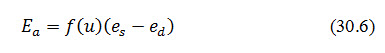
Where, f (u) = wind function; and (es-ed) = vapour pressure deficit.
It indicates that the evaporative water loss from water body can be minimized by means of obstructing the radiation heat energy coming on to the water surface and further reduction can be achieved by reducing the vapour pressure deficit or the wind speed in the microclimate.
30.3.4 Pan Evaporation Method
In this method, the rate of evaporation is measured by a pan evaporimeter. The ratio of evaporation loss measured by the evaporimeter to evaporation loss from reservoir on annual basis is constant and hardly varies from region to region. However, on short term basis, the ratio depends on a number of factors like heat storage of the evaporimeter or pan, its size and colour and above all, the depth of water in it. The evaporation loss from a pan is observed to be greater than that of the reservoir. As the size of the pan increases, the difference of the evaporation loss between the pan and the reservoir decreases. The rate of the evaporation in general, is observed to be more for deep buried pan with higher depth of water than shallow pans with less depth of water. Similarly, the evaporation from dark pans is greater than that from unpainted galvanized pans. The white coloured pan shows the least evaporation rate among other coloured pans. Covering the pan with a screen helps to reduce the pan evaporation to the equivalent of that from a reservoir. The screen helps to maintain the pan temperature uniform throughout day and night and reduces turbulence at the water surface so as to maintain uniform rate of evaporation.
30.4 Selection of Site for Evaporimeter
While selecting the site for evaporimeter near the farm pond, the following points must be taken into consideration:
-
It should be very near to the reservoir
-
It must be placed on a level ground
-
There should not be any obstruction like trees, plants, buildings or walls nearby the pan. The distance between the pan and the nearby obstruction should not be less than 10 times the height of the obstruction.
-
The pan should not get submerged due to heavy rain or flood
-
It should be located at the windward side of the reservoir
-
It is better if the highest ground water level near the pan is below 2 m depth from the ground surface
-
The site of evaporimeter should be easily accessible
30.5 Types of Evaporimeters
Evaporation pan is a simple instrument used for measuring the amount of water lost by evaporation per unit surface area in a given time interval. The commonly used evaporation pans are discussed below.
a. B.I.S Class A Pan (modified)
Class A pan evaporimeter is standardized by Bureau of Indian Standards (B.I.S) for use in India. It consists of a large cylindrical pan of 1220 mm diameter and 255 mm deep. The material of the pan is made of 1 mm thick copper sheet tinned inside and painted white outside. It has a fixed point gauge for measurement of water level. It is covered with a wire mesh. The pan sits on a white painted square wooden platform of width 1225 mm and height 100 mm above the ground level. A stilling well is provided near the fixed point gauge for providing undisturbed water surface. A thermometer is fixed to the side of the pan to measure surface temperature of water. The pointer of the gauging instrument is fixed at the highest level of water to be maintained in the pan. This is known as the reference level of water in the pan. A graduated cylinder is used to measure the volume of water to be added to the pan that is lost by evaporation in a given time so that the water level reaches the reference level. Dividing the volume of water so added with the pan surface area gives depth of evaporation loss from the pan. In case of any rainfall during two consecutive readings, two conditions may arise. The final level of water before taking the reading may be above or below the reference level. When it is above the reference level, water is removed from the pan to get back to the reference level. Depth of evaporation loss is determined by subtracting the depth of water removed from the depth of rainfall. On the contrary, when the water level is below the reference level, water is added into the pan to get back to the reference level. In this case the depth of evaporation loss is determined by adding the depth of water added to the depth of rainfall during the period. Dividing the depth of evaporation loss with the time period during which evaporation measurement is taken, evaporation rate is obtained. However, in order to obtain the evaporation loss from the free water surface of the pond or reservoir, a coefficient is used with the observed pan evaporation as presented in Table 30.1.
Table 30.1 Value of Coefficient for Various Pan Evaporation Rates (Source: Panigrahi, 2011)
|
Average evaporation rate of the pond/reservoir (mm/d) |
Value of coefficient |
|
< 5 |
0.9 – 1.10 |
|
5 - 10 |
0.80 |
|
>10 |
0.65– 0.75 |
b. U.S. Weather Bureau Class A Land Pan
It is a circular pan made of galvanized iron or monel metal. It is 1210 mm in diameter and 255 mm in depth. The pan sits over a wooden open platform 150 mm height above the ground. The platform allows free wind circulation below the pan. A hook gauge is used to measure the evaporation loss of water from the pan. A coefficient of 0.70 is used to convert the pan evaporation to the pond evaporation.
c. Colorado Sunken Pan
It looks like top open cubical container made of an unpainted galvanized iron of 914 mm square and 457 mm deep. The pan is sunk in the ground till the rim remains 51 mm above the ground surface. The reference water level in the pan is maintained at or slightly below the ground level. A hook gauge is used to measure the depth of water lost as evaporation from the pan. The measurement can also be made with the help of fixed point gauge. The hook can read up to 0.02 mm. A coefficient of 0.78 is used to convert the pan evaporation to pond evaporation.
d. U.S. Geological Survey Floating Pan
Floating pan is developed to simulate the conditions similar to that of the surrounding water in a reservoir. The pan is of cubical shape and made of galvanized iron of 900 mm square and 450 mm deep. It is supported by drum floats in the middle of a raft of size 4.25m x 4.87m and set afloat in a lake with a view to simulate the characteristics of a large body of water body. The water level in the pan and that in the surrounding reservoir is kept at the same level leaving a rim of 75 mm. Diagonal baffles are provided in the pan to reduce surging in the pan due to wave action. Wherever this pan is used, one U.S. Class A Land Pan is also installed near the floating pan to supplement the data during the missing period. The floating pan is less accessible for taking readings. Sometimes wind affects the accuracy in measurement since the waves formed by wind causes splashing of water. A coefficient of 0.80 is used to convert the pan evaporation to pond evaporation.
e. U.S. Weather Bureau Class A Floating Pan
It is a land pan but does not sit over a wooden open support. The water level inside the pan is maintained at 75 mm below the rim of the pan. Care is taken to maintain same level of water both inside and outside of the pan. A fixed index point is marked in the center of the pan. The quantity of water added to the pan to bring the water level reading up to this fixed index point gives the amount of water lost as evaporation from the pan.
30.6Reduction of Evaporation Loss from Pond
It is observed that the evaporation loss during summer months of May and June is 2-5 times more than that during winter months of December and January. Depending on location and prevailing climatic conditions, while the annual evaporation loss is maximum (300 cm) in Rajasthan, it is minimum (50 cm) in Jammu and Kashmir. Moreover, for the Indian subcontinent, annual evaporation loss from the reservoir ranges from 150-250 cm.
Evaporation is a surface phenomenon and hence, the first step to reduce evaporation loss can be achieved by reducing the surface area of the pond or the reservoir. For example, a pond with greater depth of stored water and lesser surface area would evaporate less as compared to a shallow pond with large surface area subject to both the ponds having same volume of stored water.
30.6.1 Vegetative Shade
An attempt to develop shade on the water surface by growing vegetation over the open surface of the water body is called vegetative shading. In this practice, the open surface of the pond is covered with canopy of creepers like bottle gourd (lagenaria siceraria), pumpkin, bitter gourd and cucumber etc. such that the surface water is shaded and prevented from the direct contact of sun light. The creepers are planted on the embankment and allowed to creep towards the center of the pond on a wooden platform laid across the pond. The platform is made of hardy plants like bamboo tied in a criss-cross manner. When the canopy growth covers the entire open surface of the pond, a shade is formed over the water surface and the sunlight coming onto the water is reflected back due to the albedo effect of the green leaves. Thus, the driving force for causing evaporation i.e. solar radiation is deflected and evaporation loss is reduced. This method of growing creepers on platform over the open surface of the pond is better than the attempt of reducing evaporation loss by growing floating aquatic plants as in case of latter the plants consume a lot of water from the pond to meet their transpiration requirements.
30.6.2 Monomolecular Film
It is a film of one molecule thick also called as monolayer. Chemicals either in the form of powder or solution is spread over the water surface which deflects the energy input of the sun as a result of which evaporation is reduced. Alcohols such as cetyl alcohol [CH3 (CH2)15OH] also called as hexadecanol and stearyl alcohol (octodecanol) are used to form a monomolecular film on contact with water which is sufficiently enduring in field conditions. The invisible film is non-toxic in nature and reduces evaporation by 50-60% at an average wind speed of 16.55 km/hr. The advantage of this film is that it is not opaque and so, does not restrict the path for movement of rainwater, oxygen and sun light through the water surface. However, the limitation of these monomolecular films is that they get diluted in water quickly and then become ineffective to reduce the evaporation of water.
30.6.3 Wind Breaks
Increased turbulence on the water surface is one of the factors to accelerate evaporation loss from the water body. Wind action is solely responsible for such turbulence on water surface. Hence, continuous wind or wind at high speed over the pond or reservoir is likely to increase the evaporation loss. In such cases, developing wind breaks, a physical barrier to oppose the wind blow, by growing tall trees at close spacing around farm pond is expected to minimize the turbulence effect and reduce the evaporation loss. But these wind breaks are useful only for small ponds. It is found out that a reduction of wind velocity by 25% can reduce the pond evaporation loss by only 5%. It indicates that the measure is not very much effective in reduction of evaporation loss.
30.6.4 Covering Pond Water with Shading Materials
Like vegetative shading, many other artificial materials or sheets can be used as effective barriers to prevent the direct sun light coming onto the water surface and thereby, reduce the evaporation loss. Such shading materials may be plastic films, thatches, paddy straw, sugarcane trash etc. When they are used to cover the water surface, the sun light cannot penetrate through and consequently, the evaporation loss is reduced. However, the effectiveness of the shading material in reducing evaporation from the pond depends on its quality and the percentage cover of the open surface area of the pond. Evaporation loss is likely to come down to minimum under complete coverage (100%) of the open surface and thus, partial coverage would have reduced effect on evaporation rate of the pond.
Some other shading materials used for reduction of evaporation loss are dye mixed with pond water, plastic mesh and sheet, polystyrene beads and sheet, white spheres and white butyl sheet etc. Out of these materials, polystyrene raft, plastic sheet and foamed butyl rubber are the best ones since they are reported to reduce the evaporation loss by more than 90%. However, these materials are very expensive and unlikely to make the project cost effective. Therefore, these materials are not applied for reducing evaporation loss from on-farm ponds instead they are used in drinking water projects to reduce evaporation loss.
30.7Seepage Losses in Farm Pond
Harvested water in on-farm ponds in water scarce areas is a precious commodity and care should be taken to conserve it for a longer period with minimum loss. Two major means of the loss of harvested water from such ponds are evaporation and seepage. Most of the ponds used for irrigation purpose are unlined and without any measure to reduce evaporation loss. However, the loss due to seepage is more pronounced than that due to evaporation. A study reveals that seepage loss in unlined ponds accounts for about 45% of the total storage and the evaporation loss accounts for only 25% (Guerra et al., 1990). This loss is significant when the pond is underlain by porous strata or when the bed material of the pond consists of coarse textured soil. Small farm ponds constructed in coarse texture soils; especially in arid and semi-arid regions are found to get dry completely just after the withdrawal of monsoon. However ponds constructed in heavy soils are found to have less seepage losses. In general the seepage loss in unlined small farm ponds depends upon the water table position below the ground surface, soil type at the site of excavation and hydraulic gradient available between the pond water level and water level of adjacent areas. It is observed that the seepage loss in newly constructed pond is very high and it decreases gradually with progress of time as silt deposition takes place in the pond.
30.8 Methods to Reduce Seepage Losses
Seepage loss from farm ponds can be reduced broadly by two ways. They are (i) reducing wetted surface area of the pond and (ii) using a cost effective sealant.
30.8.1 Reducing Wetted Surface Area of Pond
Seepage from the pond increases with increase in wetted area of a pond. Hence, special considerations must be given to minimize the wetted area per unit of storage capacity during design of the pond. This may be achieved by making the side slopes steep and/or decreasing the depth of the pond. In case of large ponds, division of the pond into two or more compartments also helps in reduction of seepage loss. By doing so the wetted area and top water surface area of the pond are considerably reduced resulting in reduction of seepage and evaporation loss, respectively, to a great extent.
30.8.2 Use of Sealants
A newly constructed pond has self-sealing property by deposition of silt. The runoff of the catchment carries some silt and clay which gets deposited in the side and bottom of the pond and clogs the pore spaces of the soil. Consequently, the flow through the side and bottom of the pond is reduced and seepage loss is checked. Studies conducted at Dehradun and Rajkot of India reveal that seepage from a newly dug out pond reduced to a very low rate due to silting in a period of 8 years. Silting also reduces seepage rate in brick lined pond.
A simple way to reduce water seepage, particularly if the pond bottom is very dry, hard and has open cracks in it, is to break the soil structure of the pond bottom before filling the pond with water. This is common practice is called puddling. It is accomplished through making the pond bottom saturated with water, allowing the water to be soaked into soil just enough to permit working and then, breaking the soil structure by puddling with a plough.
A number of sealants/lining materials are now available to reduce the seepage loss. Lining of the pond, though costly, can reduce the seepage loss and improve the effective storage of the pond. Different lining materials used to reduce the seepage loss are plastic film, soil cement lining, bitumen lining, clay lining, cow dung lining, brick cement lining etc. Lining with brick masonry or cement mortar lining is most expensive but effective among them. Lining for reduction of seepage losses is feasible only for small pond. Descriptions of a few lining materials used for seepage control in the pond are given below.
1. Clay Lining
Natural clay can be used for lining with varying degree of efficiency, especially when lower cost is desirable. Clay lining can be applied in two methods:(i)by placing a blanket of relatively impervious clay of 15-30 cm thick over or within the permeable bed and slides of the pond and(ii)by dispersing clay in the water to form clay mud and filter it out to seal off the pores in the permeable sides and bottom of the pond. Alkali soils having poor infiltration rates, if available in the vicinity of the pond can be preferred for lining to control seepage in farm ponds. Burnt clay tiles can also be used as lining material for reducing seepage loss. Percentage of saving of water due to seepage by these tiles is about 98.8% more than the earthen materials. Studies reveal that a lining of soil cement plaster at ratio 5:1 is ideal from the points of cost and efficiency. For good results, the mixture of soil and cement should be mixed well, laid out and compacted. It should be cured for seven days with moist soil cover. The limitation of this lining material is that,
it is not weather resistant
its life is comparatively short and
repair and maintenance cost is relatively higher.
2. Cement Concrete Lining
Cement concrete lining to reduce seepage loss is stronger and more stable than any other lining material. Though the initial investment for such lining is more, its repair and maintenance cost is very less and it gives long service. Concrete mixture usually recommended for lining is 1:3:4 (cement: sand: gravel) with 4–5 cm thickness. The sides and bottom of the structure should be compacted at suitable moisture content. When concrete hardens, it shrinks resulting in development of cracks. Apart from adequate curing, joints must be provided at a distance of 2 m in order to localize and control the cracks. Cement concrete lining can withstand higher velocity of flow (>2.5 m/sec) because of its greater resistance to erosion and is therefore preferred to any other type of lining.
3. Asphalt Lining
Asphalt also known as bitumen is sticky, black in colour and highly viscous liquid or semi-solid form of petroleum. It acts as a binding material in road construction. When it is mixed with sand and gravel, it forms asphalt concrete and this is used as a lining material in ponds. Asphalt concrete lining is cheaper than cement concrete lining. Its life span ranges from 10-20 years. There are two types of prefabricated asphalt melts found to be promising in seepage control. They are (i) Gunny (coarse sack cloth made of jute) reinforced asphalt melt and (ii) Synthetic cloth reinforced asphalt melt. Between the two, the former has proved to be a better lining material in terms of reducing seepage loss from ponds.
4. Brick Lining
In brick lining, the bricks are joined together with soil cement plaster. It requires relatively less investment as compared to cement concrete ling. Brick lining is easier to construct and requires less technical knowledge. It requires less cement as compared to concrete lining and can be laid out without use of any machinery. However, it is not that effective in seepage control as compared to cement concrete lining.
5. Bentonite Lining
Bentonite is fine textured colloidal clay with as much as 90 per cent of montmorillonite. There are two types of bentonite; high swelling and low swelling. While sodium is the main constituent in high swelling bentonite, calcium makes it for low swelling one. When exposed to water, dried bentonite absorbs several times its own weight of water; at complete saturation, it swells as much as eight to twenty times its original dry volume. The dry bentonite is mixed with the top 15 cm soil layer thoroughly at a rate of 5 – 15 kg/m2. The advantages of bentonite lining are its low cost, easy installation procedure and long lasting solution to excessive seepage. Main disadvantages of this lining are listed below:
it is more laborious to apply than a butyl membrane
it can be disrupted by cattle or eroded by running water
burrowing animals such as crayfish or crabs can make rupture in such lining
bentonite treatment is not advisable in highly alkaline soils
6. Alkali Soil Lining
Application of alkali soil lining in small ponds is observed to be an effective lining material to reduce seepage loss. In this practice, a layer of alkali soil of about 5 cm thickness is spread on the sides and bottom of the pond for effective seepage control.
7. Soil Deflocculants
A deflocculant is a chemical additive to prevent a colloid from coming out of suspension. It is used to reduce viscosity or prevent flocculation and is sometimes called a dispersant. Soil deflocculants like sodium carbonate, sodium chloride, and tetrasodium polyphosphate and sodium tripolyphosphate are used for reducing permeability of pond surfaces. Sodium chloride and sodium polyphosphate perform effectively up to 6 and 8 months, respectively.
8. Gleization
When the pond bottom is too permeable, it is required to create an impervious biological plastic layer in the bottom and on the sides of the pond in order to reduce seepage loss. Such an impervious layer is called a gley, and the process of its formation is called gleization. Step by step procedure of gleization is as follows:
The pond bottom is prepared by clearing it of all vegetation, sticks, stones, rocks and filling all cracks, crevices and holes with well-compacted impervious soil.
Cleaned surface is completely covered with moist animal manure spread in an even layer about 10 cm thick.
The manure is covered completely with a layer of vegetal material, preferably broad leaves of banana. Dried grass, rice straw, soaked cardboard or paper, etc. can be used for this purpose.
A layer of soil about 10 cm thick is placed over the vegetal cover.
All the materials are moistened and compacted properly.
Fill up the pond with water slowly.
9. Chemical Sealants
U.S Bureau of Reclamation studied many chemicals including resins, silicones, linings but none was found suitable in seepage control. Even cationic asphalt emulsion, petroleum emulsion and resinous polymers were tested and found to be short lived and affected by wetting, drying and erosion.
10. Polythene Lining
Currently, low-density polyethylene (LDPE) sheets, cross laminated plastic tarpaulins of various thicknesses are widely used as lining materials in ponds to reduce seepage loss. Careful placing and burying of the polyethylene sheet under at least 15 cm thick soil layer gives full proof sealing and long expected life. LDPE lining is a cheap and effective measure for reducing seepage loss from unlined water harvesting structures. All India Coordinated Research Project for Dryland Agriculture, Hyderabad, India reported that 91% of seepage loss can be controlled by lining the tanks with LDPE sheets under brick load on the steps (Vijayalakshmi et al., 1982). Another study reveals that with 600 gauge LDPE sheet covered by 20 cm thick soil layer on sides and bottom the seepage loss reduced to 7 L m-2 day-1 (Gajriet al. 1983). Combination of LDPE sheet (800 gauge thickness) at the bottom and 75 mm thick brick cement lining on the sides of the pond can reduce the seepage loss from 520 to 12.71 L m-2 day-1 (Verma and Sarma, 1990).
However, it is important to note that before using any lining materials for seepage control in the pond, the economic analysis relating to the life of the pond and cost of lining materials must be taken into account. At the same time, the amount of irrigation water saved by reduction of seepage loss and use of the same in increasing the crop production and other associated benefits must also be considered to assess the economic feasibility of the technology.
Key words: Seepage, Evaporation, Silting , Sealants
References
Panigrahi, B. 2011. Irrigation systems engineering. New India Publishing Agency.
Guerra, L.C., Watson, P.G. and Bhuiyan, S.I. (1990). Hydrological Analysis Of Farm Reservoirs in Rainfed Areas. Agric. Water Manage., 17(4):351-366.
Suggested Readings
Verma, H.N. and Sarma, P.B.S. (1990). Design of storage tanks for water harvesting in rainfed areas. Agric. Water Manage. 18(3): 195-207.
Vijayalaxmi, K., Vittal, K.P.R. and Singh, R.P. (1982). Water harvesting and reuse. In a decade of dryland agriculture research in India (1971-80). AICRPDA (ICAR):103-119.
Last modified: Tuesday, 4 February 2014, 10:35 AM